Passive thermoacoustic cooling apparatus

Inactive Publication Date: 2006-11-30
NAT TAIWAN UNIV
View PDF1 Cites 14 Cited by
  • Summary
  • Abstract
  • Description
  • Claims
  • Application Information

AI Technical Summary

Benefits of technology

[0010] The present invention further provides a thermoacoustic heat dissipation apparatus for passive cooling of a heat source, said apparatus operating solely on said heat source to be cooled without any additional energy source, said apparatus comprising at least one temperature difference element having a hot end and a cold end; a heat conduction element connected to said hot end of said temperature difference element and to said heat source for conduction of heat from said heat source to said temperature difference element; and a resonance cavity system comprising an aggregation of a plurality of cavity casings each defining a resonance cavity therein, said resonance cavity system internally enclosing and embedding said temperature difference element and said heat conduction element; wherein said temperature difference element being positioned inside each of said resonance cavities at a location sustaining a thermoacoustic effect by the generation of a standing wave therein; and said temperature difference element having an air-passing porous body structure allowing connectivity between the air at the hot and cold ends thereof inside said resonance cavity.

Problems solved by technology

Active, heat dissipation systems may be optimized for cooling but consumes additional power and are frequently accompanied by problems such as mechanical vibration and increased size.
On the other hand, passive devices may be simple and power-saving, yet they are limited in their effectiveness of heat dissipation within the realm of reasonable physical sizes and dimensions of both the devices themselves and the equipments they serve.

Method used


Image

  • Passive thermoacoustic cooling apparatus
  • Passive thermoacoustic cooling apparatus
  • Passive thermoacoustic cooling apparatus

Examples


Embodiment Construction

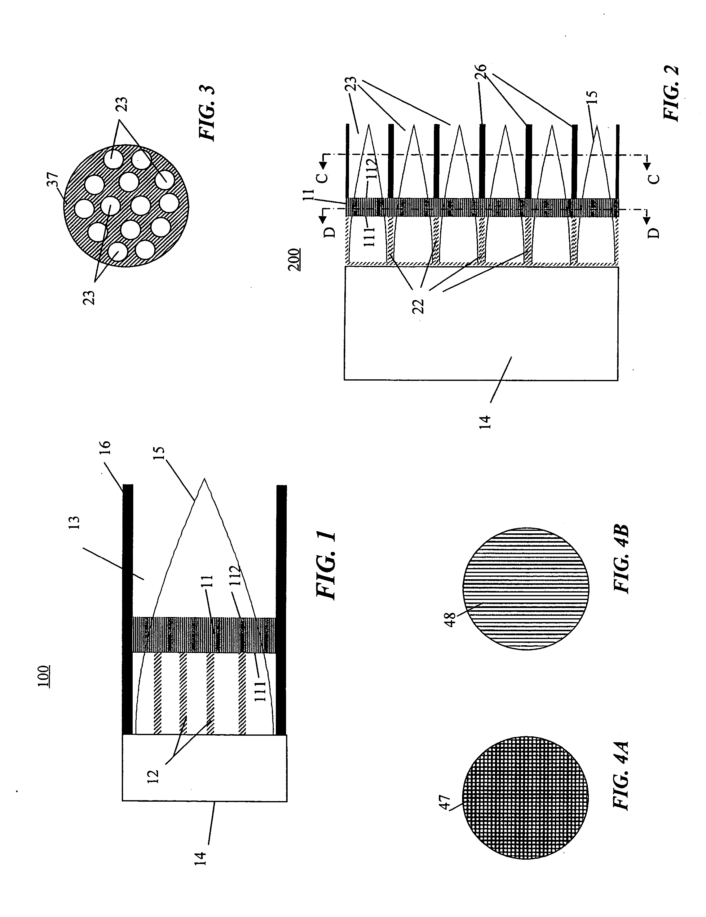
[0018] A preferred embodiment of the thermoacoustic heat dissipation apparatus in accordance with the present invention is schematically illustrated in FIG. 1. The thermoacoustic heat dissipation apparatus identified by 100 has a heat conduction element 12 and a temperature difference element 11 generally enclosed in a resonance cavity 13. Standing waves generated as a result of thermoacoustic effect by the resonance cavity 13 appear within the space generally defined by the cavity casing 16. One end of the generally elongated resonance cavity 13 as illustrated in the drawing is closed by a heat source 14 to be cooled. The other end of the cavity 13 remains open.

[0019] Longitudinal length of the resonance cavity 13 can be selected to be a quarter of the acoustic wavelength of the basic frequency at which resonance tends to occur. Air pressure distribution for the standing wave in the resonance cavity most likely to appear is schematically shown in FIG. 1 as curve 15. Curve 15 repre...


PUM


Abstract

A passive thermoacoustic cooling apparatus for cooling of components such as miniaturized microelectronics is disclosed. The passive thermoacoustic cooling apparatus includes resonant cavities, a temperature-difference element and a heat conduction element. The temperature-difference element is integrated with the system of resonant cavities for conversion of heat into acoustic power. The heat conducting element connects a heat source to the temperature-difference element, which transmits heat from the source to one end of the temperature-difference component. Due to established temperature gradient across hot and cold ends of the temperature-difference element, acoustic standing wave arises in the resonant cavity system. Forced air convection is thereby generated to cool the heat source.

Description

BACKGROUND [0001] 1. Field of the Invention [0002] The present invention relates in general to a thermoacoustic heat management apparatus. More particularly, this invention relates to a passive thermoacoustic heat dissipation apparatus for the cooling of equipment by air convection induced by the equipment itself via thermoacoustic effect. [0003] 2. Description of the Related Art [0004] Heat dissipation devices for semiconductor integrated circuit devices such as microprocessors can be generally categorized as active and passive devices. Fans driven by electric motors or circulating work fluids circulated by pumps are examples of active heat dissipation systems, and simple heat sinks with structured fins aimed at enlarging air contact surface area are examples of passive devices. A motor driven fan requires an active supply of electric power for the fan blades to forcefully circulate the airflow inside the equipment so that heat generated by the equipment can be removed. By contrast...

Claims


Application Information

Patent Timeline
IPC IPC(8): F25B9/00
CPCF25B9/145F25B2309/1416F25B2309/1403
Inventor HSING, PEN -YUANHUANG, WEI-KANGSHU, TSENG-YUWU, MING-TECHANG, LIANG-CHAOSHENG, PAO-JENGLEE, CHIH KUNGCHENG, CHIH-CHIANGHSIAO, WEN HSIN
Owner NAT TAIWAN UNIV
Why Eureka
Try Eureka