Metal hydride hydrogen storage system

a technology of metal hydride and hydrogen storage system, which is applied in the direction of separation process, dispersed particle separation, chemistry apparatus and processes, etc., can solve the problems of lack of acceptable hydrogen storage medium, and inability to meet the needs of hydrogen storag

Inactive Publication Date: 2006-11-30
TEXACO OVONIC HYDROGEN SYST LLC
View PDF14 Cites 23 Cited by
  • Summary
  • Abstract
  • Description
  • Claims
  • Application Information

AI Technical Summary

Benefits of technology

[0016] Disclosed herein, is a metal hydride hydrogen storage unit comprising a pressure containment vessel having a longitudinal axis, a plurality of cells at least partially filled with a hydrogen storage alloy powder, a plurality of primary modular blocks containing at least a portion of the plurality of cells, and a plurality of fins wherein each of the fins are disposed between two of the primary modular blocks. The plurality of modular blocks and/or the plurality of fins may be radially disposed inside the pressure containment vessel about the longitudinal axis of the pressure containment vessel. The plurality of fins may have a corrugated or grooved configuration. The plurality of cells may have an open top, an open bottom, and a cell wall. The hydrogen storage material may be retained in the plurality of cells via a porous filter material disposed at the top and/or bottom of each of the plurality of cells. The plurality of cells may have a circular configuration or a polygonal configuration. The primary modular blocks preferably have a height less than one half of the inner diameter of the pressure containment vessel. The pressure containment vessel may be wrapped in a fiber reinforced composite material.
[0017] The metal hydride hydrogen storage unit may further comprise one or more heat exchanger tubes at least partially disposed within the pressure containment vessel, the one or more heat exchanger tubes being in thermal communication with the hydrogen storage material.
[0018] The metal hydride hydrogen storage unit may further comprise an axial channel disposed about the longitudinal axis of the pressure containment vessel. One or more secondary blocks including at least a portion of the plurality of cells may be disposed in the axial channel. The one or more secondary modular blocks may have a cylindrical configuration.
[0019] In a first embodiment of the present invention, a hydrogen storage material occupies at least 60% of the available interior volume of the pressure containment vessel, preferably 70% of the available interior volume, and most preferably 80% of the available interior volume. Upon cycling between hydriding and dehydriding, the rate of increase in the average equivalent pressure exerted on the sidewall is less than 25 psi over at least 20 of the cycles, the hydriding portion of each of the cycles including the step of charging said hydrogen storage material to at least 60% of its maximum storage capacity. Preferably, the rate of increase of equivalent pressure exerted on the sidewall is less than 25 psi per cycle of hydriding and dehydriding over at least 45 of the cycles. More preferably, the rate of increase of equivalent pressure exerted on the sidewall is less than 25 psi per cycle of hydriding and dehydriding over at least 65 of the cycles. Preferably, the hydriding po

Problems solved by technology

While the world's oil reserves are rapidly being depleted, the supply of hydrogen remains virtually unlimited.
Furthermore, hydrogen, although presently more expensive than petroleum, is a relatively low cost fuel.
While hydrogen has wide potential application as a fuel, a major drawback in its utilization, especially in mobile uses such as the powering of vehicles, has been the lack of acceptable hydrogen storage medium.
Storage of hydrogen as a compressed gas involves the use of large and bulky vessels.
Additionally, transfer is very difficult, since the hydrogen is stored in a large-sized vessel; amount of hydrogen stored in a vessel is limited, due to low density of hydrogen.
Furthermore, storage as a liquid presents a serious safety problem when used as a fuel for motor vehicles since hydrogen is extremely flammable.
Moreover, liquid hydrogen is expensive to produce and the energy necessary for the liquefaction process is a major fraction of the energy that can be generated by burning the hydrogen.
If the material fails to possess any one of these characteristics it will not be acceptable for wide scale commercial utilization.
Heat ineffectively removed can cause the hydriding process to slow down or terminate.
This becomes a serious problem which prevents fast charging.
Another recognized difficulty with hydride storage materials is that as the hydrogen storage alloy is hydrided, it will generally expand and the alloy particles will swell and, often crack.
When hydrogen is released, generally on application of heat, the storage material or hydrided material will shrink and some particles may collapse.
The comminution process results in a decrease in the powder density of the storage material.
Highly packed localized high density regions of hydrogen storage alloy po

Method used


Image

  • Metal hydride hydrogen storage system
  • Metal hydride hydrogen storage system
  • Metal hydride hydrogen storage system

Examples


example

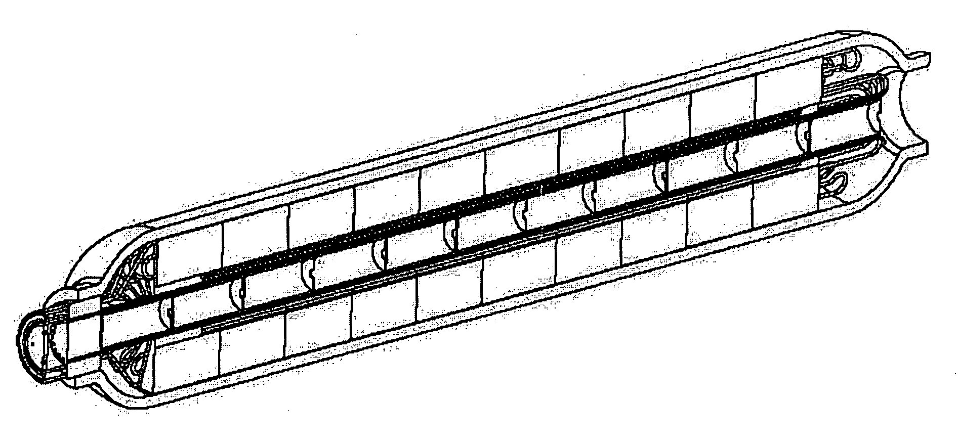
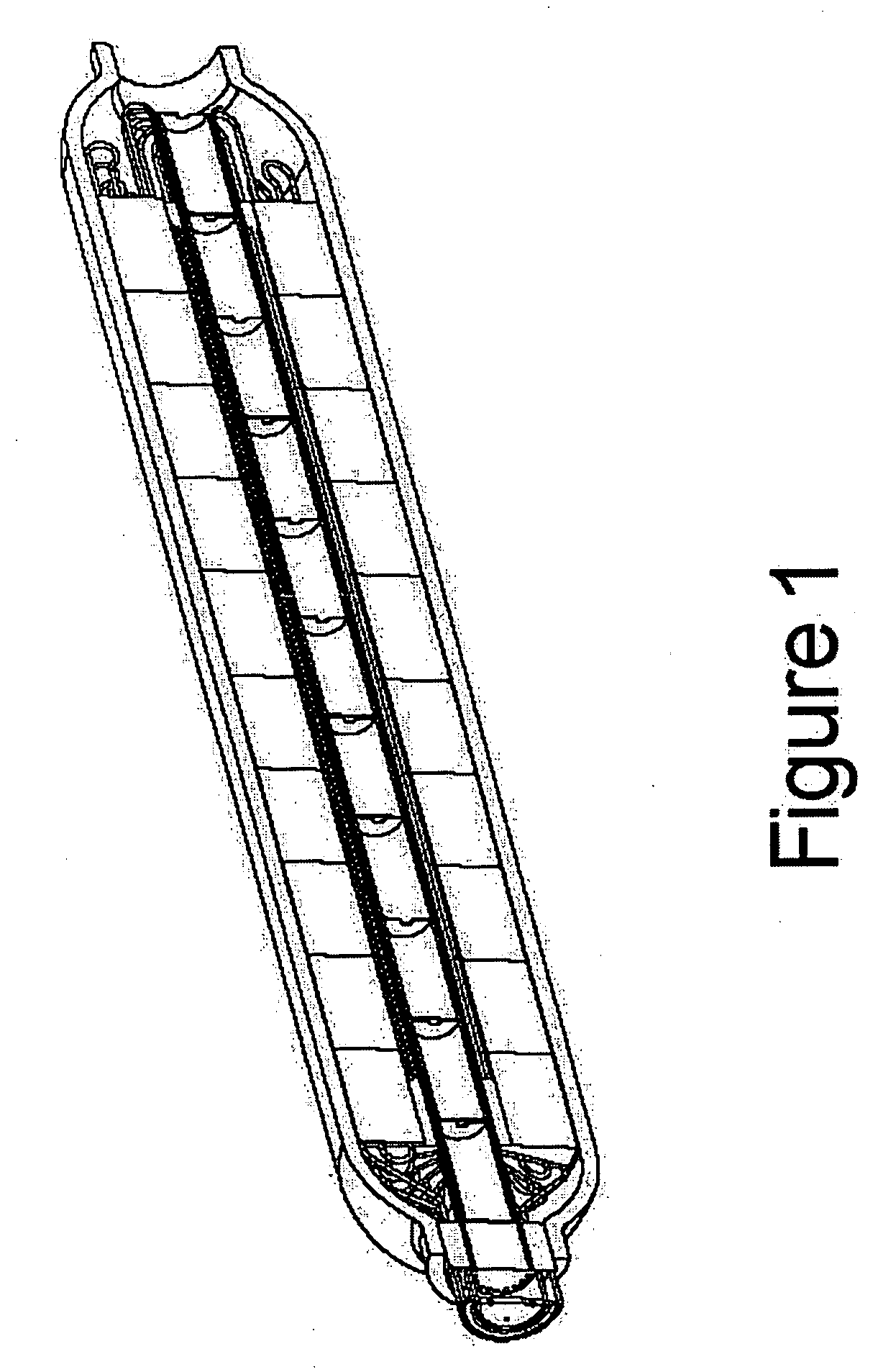
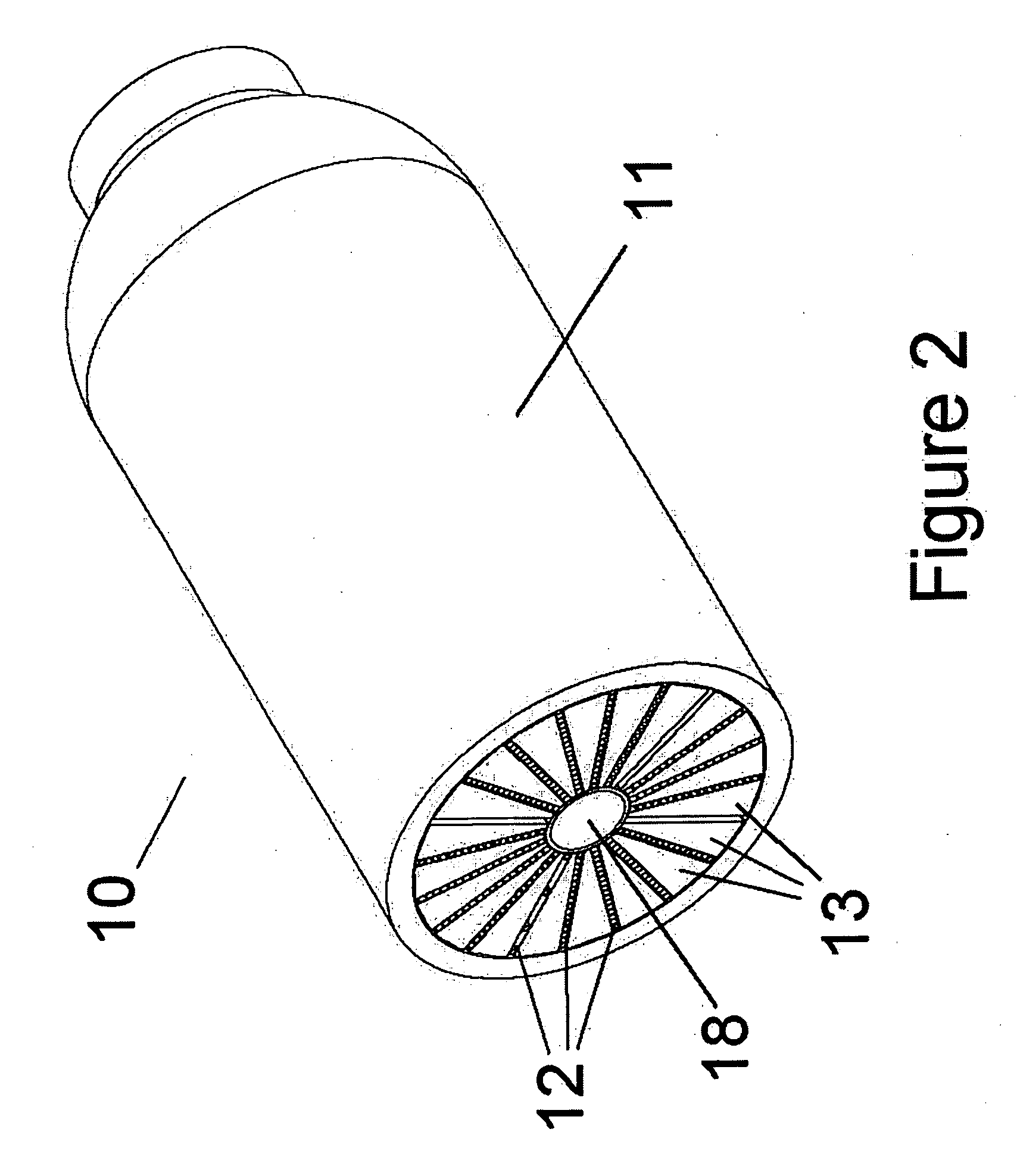
[0046] In this example, a beneficial reduction in stress at the interior wall of a pressure containment vessel of a hydrogen storage unit according to the present invention is demonstrated. The hydrogen storage unit includes a pressure containment vessel having an outside diameter of approximately 3.5 inches and a length of approximately 12 inches. The vessel has a central portion that is cylindrically shaped and upper and lower end portions that are rounded. One of the end portions was equipped with an inlet opening to permit access to the interior of the vessel and to enable the introduction of hydrogen gas into the vessel.

[0047] The interior of the vessel was equipped with radially disposed cells for supporting and housing a hydrogen storage alloy powder. The cells were formed as corrugations in metal disks that were inserted into the vessel with centers aligned along the central longitudinal axis of the vessel. Both ends of each of the radially disposed cells were open to permi...


PUM

PropertyMeasurementUnit
Fractionaaaaaaaaaa
Fractionaaaaaaaaaa
Fractionaaaaaaaaaa

Abstract

A metal hydride hydrogen storage unit utilizing compartmentalization to maintain a uniform metal hydride powder density thereby reducing stress on the vessel due to repeated cycling. An hydrogen storage alloy powder occupies at least 60% of the available interior volume of the hydrogen storage unit. Upon cycling of the hydrogen storage alloy powder between hydriding and dehydriding, the rate of increase in the average equivalent pressure exerted on the sidewall is less than 25 psi over at least 20 cycles, the hydriding portion of each of the cycles including the step of charging said hydrogen storage alloy powder to at least 60% of its maximum storage capacity.

Description

CROSS REFERENCE TO RELATED APPLICATIONS [0001] The present application is a continuation-in-part of, and is entitled to the benefit of the earlier filing date and priority of, co-pending U.S. patent application Ser. No. 11 / 138,864, which is assigned to the same assignee as the current application, entitled “MODULAR METAL HYDRIDE HYDROGEN STORAGE SYSTEM,” filed May 26, 2005 for Myasnikov et al., the disclosure of which is hereby incorporated by reference.FIELD OF THE INVENTION [0002] The present invention generally relates to hydrogen storage systems. More particularly, the present invention relates to hydrogen storage systems utilizing a hydrogen storage alloy to store hydrogen in metal hydride form. BACKGROUND [0003] In the past considerable attention has been given to the use of hydrogen as a fuel or fuel supplement. While the world's oil reserves are rapidly being depleted, the supply of hydrogen remains virtually unlimited. Hydrogen can be produced from coal, natural gas and oth...

Claims


Application Information

Patent Timeline
IPC IPC(8): B01D53/02
CPCB01D53/0407B01D53/0415B01D2253/1126B01D2253/3425B01D2257/108B01D2259/40088Y02E60/327B01D2259/4566C01B3/0005C01B3/0031C01B3/0036C01B3/0042C22C22/00B01D2259/4525Y02E60/32
Inventor OVSHINSKY, STANFORD R.MYASNIKOV, VITALIYGERASIMOV, ALEXANDERSOBOLEV, VALERIE
Owner TEXACO OVONIC HYDROGEN SYST LLC
Why Eureka
Try Eureka