Adsorption element

Active Publication Date: 2006-11-30
MANN HUMMEL GMBH
View PDF13 Cites 9 Cited by
  • Summary
  • Abstract
  • Description
  • Claims
  • Application Information

AI Technical Summary

Benefits of technology

[0013] The support grid has the advantage of supporting and stiffening the adsorption medium over a large area without substantially reducing the adsorption capacity. This makes it possible to use adsorption media that are mechanically relatively unstable and to exclude the risk that particles are torn out of the medium while the engine operates in suction mode. This is important especially when the adsorption element is disposed on the filtered side of the intake tract.
[0014] According to yet another embodiment of the invention the adsorption element has a core, which is stabilized by a support member. Folding the medium into a hollow shape creates a cavity in the center in which a support member can be disposed. This support member may for instance be a center tube that contacts, and may also be connected to, the crests of the folds. The support member has the role of mechanically supporting the adsorption element and should allow radial flow. The support member may, for example, be embedded into an end disk at one end face. As an alternative, the support member may also protrude axially over the adsorption medium and simultane

Problems solved by technology

Thus, the automobile manufacturer is confronted with the problem of retaining the hydrocarbons that flow back when the engine is shut off.
A drawback in this embodiment is that the spiral arrangement makes the adsorption element

Method used


Image

  • Adsorption element
  • Adsorption element
  • Adsorption element

Examples


Example

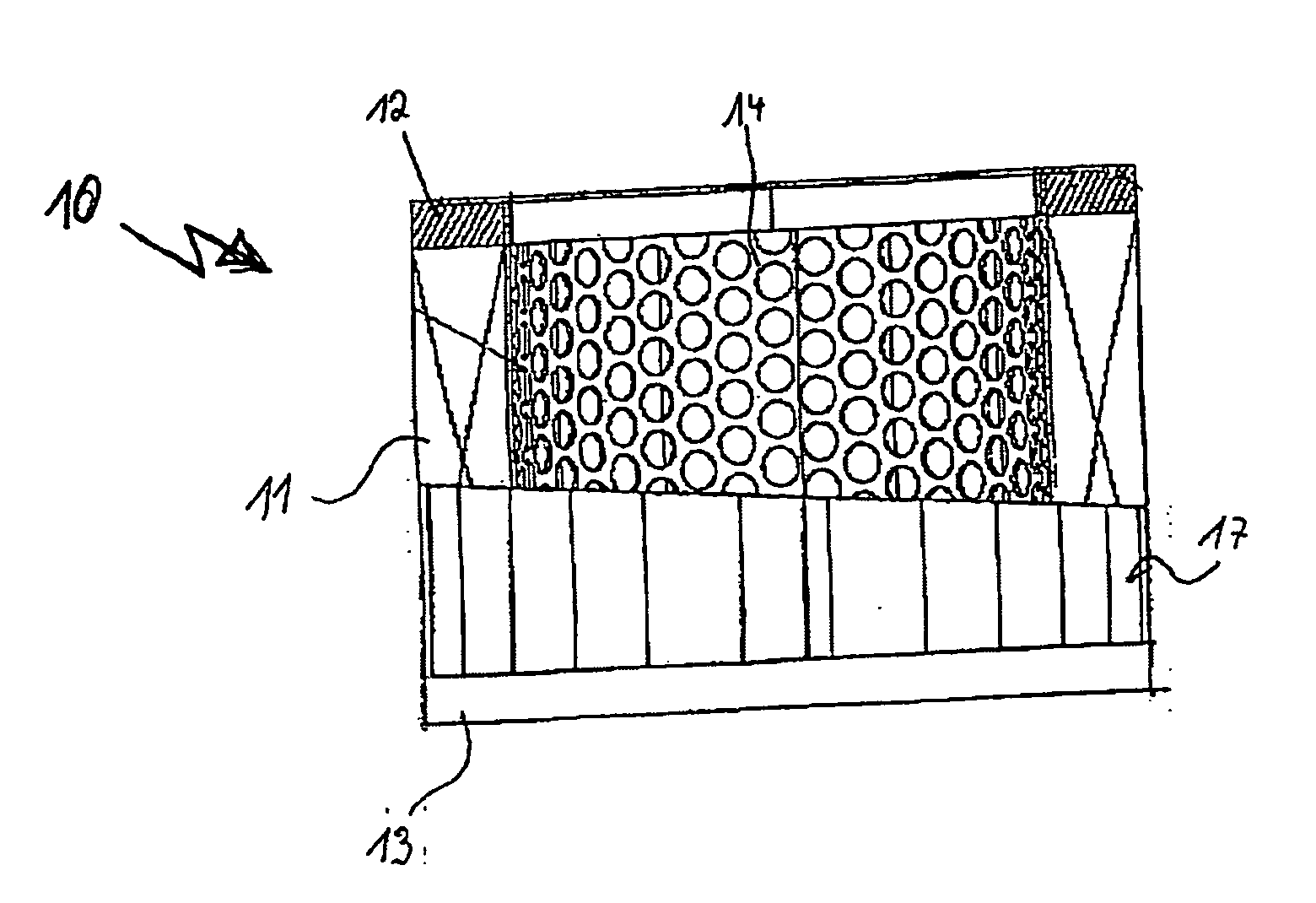
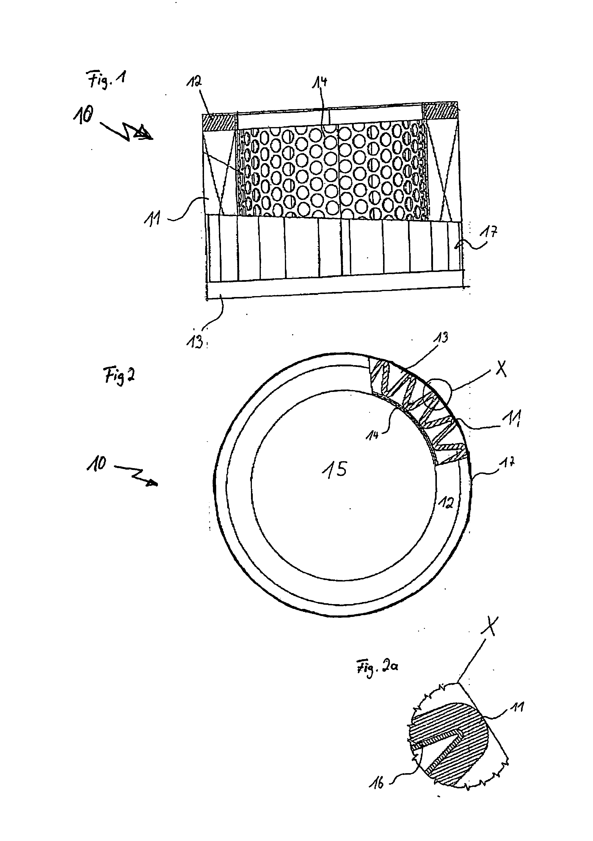
[0024]FIG. 1 shows an adsorption element 10 in which an adsorption medium 11 is disposed between a first end disk 12 and a second end disk 13. The adsorption medium 11 is folded into a hollow cylinder and is supported along its radially inner surface by a center tube 14. At both axial end faces of the cylinder, the longitudinal ends of the center tube 14 and the adsorption medium 11 are embedded in the end disks 12, 13. The end disks 12, 13 may, for instance, be made of single- or multi-component synthetic resin materials (i.e., plastics), which are introduced into a shell mold in liquid form and cured after embedding of the adsorption medium 11 and the center tube 14. This makes it possible to produce an end disk from polyurethane foam, a polyurethane resin adhesive or a polyamide casting, for example.

[0025]FIG. 2 shows the hollow cylindrical adsorption element 10, which encloses the flow cross section 15. Components corresponding to those of FIG. 1 are identified by the same refe...


PUM

PropertyMeasurementUnit
Flow rateaaaaaaaaaa
Adsorption entropyaaaaaaaaaa

Abstract

An adsorption element for adsorbing gases and vapors from the gaseous atmosphere in the intake tract of an internal combustion engine. The adsorption element is disposed within a wall of a flow cross section carrying the intake air, has a planar adsorption medium along which the intake air flows, and is pleated to create folds in longitudinal direction of the intake stream.

Description

BACKGROUND OF THE INVENTION [0001] The present invention relates to an adsorption element for adsorbing vapors and / or gases from an air duct such as the air intake tract of an internal combustion engine. [0002] An important development goal for modern internal combustion engines is a reduction of emissions. Increasing air pollution caused by the internal combustion engines of motor vehicles has led to the development of different testing and rating methods. These increased requirements are forcing automobile manufacturers, particularly in the American market, to minimize the hydrocarbons that leak from the engine's intake tract when a gasoline engine is shut off. It is expected that in the future the limits for these hydrocarbons will be further reduced and that the scope of application will be extended to an increasing number of countries. Thus, the automobile manufacturer is confronted with the problem of retaining the hydrocarbons that flow back when the engine is shut off. To ac...

Claims


Application Information

Patent Timeline
IPC IPC(8): B01D53/02
CPCF02M25/0854F02M35/10222F02M35/024
Inventor WEBER, OLAFWILD, STEPHANWENZEL, WOLFGANGVOLKMER, DANIELSOHNEMANN, JENSROHRMEIER, JOSEFSCHWINGHAMMER, ALFONSPFEIFFER, FRANK
Owner MANN HUMMEL GMBH
Why Eureka
Try Eureka