
Fixed-volume inflation system for balloon catheters

a balloon catheter and inflation system technology, applied in the field of balloon catheter inflation systems, can solve the problems of organ trauma, more sophisticated and expensive than is necessary to achieve, and achieve the effects of reducing accidental human errors, high molecular density, and saving care-giver tim

Inactive Publication Date: 2006-11-30
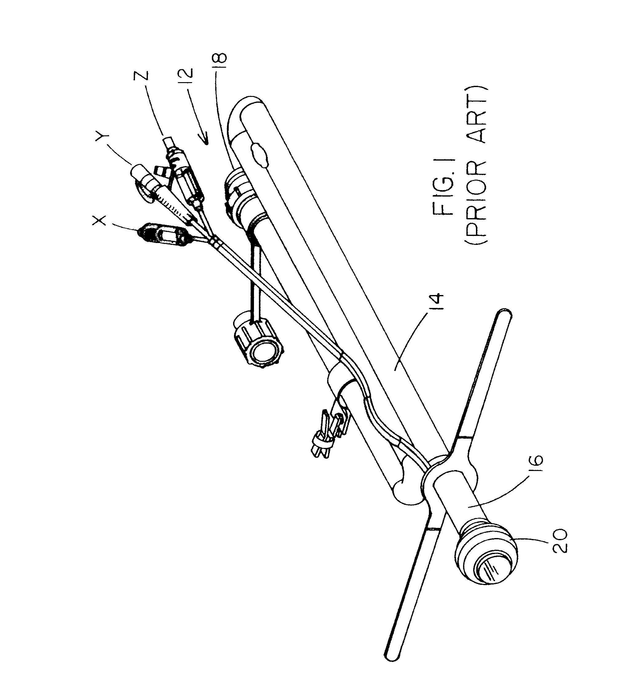
HOLLISTER INCORPORAED
View PDF16 Cites 29 Cited by
  • Summary
  • Abstract
  • Description
  • Claims
  • Application Information

AI Technical Summary

Benefits of technology

[0009] A further advantage of the present invention is that diffusion of the inflation media through the balloon membrane does not occur because the balloon membrane is constructed of a non-permeable balloon membrane material and / or the inflation media is a high molecular density substance that cannot diffuse through the membrane. Because the membrane material is non-permeable the system still has the advantage of using standard water based fluids for inflation / expansion purposes. The result of this impermeability is that the catheter retention balloon does not have to be checked repeatedly, thereby saving care-giver time and reducing accidental human errors as they are commonly seen during routine manipulations of the system.
[0010] Still further, the new system has the advantage of being volume-regulating, not pressure-regulating, and is therefore not affected (i.e., does not lose volume) by transient pressure changes in the patient's organ (e.g., contraction of the rectum).
[0011] Accordingly, in keeping with the above goals and advantages, the present invention is, briefly, an inflation system for a balloon catheter assembly having a main catheter with a first end and a second end. The first end of the main catheter is proximally disposed within a patient in normal use position and has an inflatable cuff disposed thereon, to sealingly retain the main catheter in normal use position within a patient. The second end of the main catheter is disposed distally and external of a patient during normal use position. The system includes an inflation tube, the inflation tube having a first end and a second end, the first end of the inflation tube being connectable to an inflation fluid reservoir and the second end of the inflation tube being connectable to and opening into the cuff on the main catheter, to thereby permit a fluid reservoir to be placed in fluid communication with the cuff. A fluid reservoir is connectable to the inflation tube and is fillable with cuff inflation fluid only to a predetermined, fixed volume, to thereby permit no more than such predetermined, fixed volume of fluid to be transferred from the fluid reservoir to the cuff during use of the system, to prevent over-inflation of the cuff and thereby avoid potential trauma to the patient.
[0012] The invention is further, briefly, a bowel management assembly having a closed, fixed-volume inflation system. The assembly includes a main catheter for bowel drainage with a first end and a second end, the first end of the main catheter to be disposed within a patient's rectum during use, and the second end of the main catheter to be disposed distally and external of a patient during normal use position. An inflatable and deflatable cuff is connected around the first end of the main catheter, to retain the main catheter in operative position within a patient during use, when the cuff is in an inflated configuration. The closed, fixed-volume inflation system includes an inflation tube, the inflation tube having a first end and a second end, the first end being connectable to an inflation fluid reservoir and the second end being connectable to and opening into the cuff on the main catheter, to thereby permit a fluid reservoir to be placed in fluid communication with the cuff. A fluid reservoir is connectable to the inflation catheter and is fillable with cuff inflation fluid only to a predetermined, fixed volume, to thereby permit no more than such predetermined, fixed volume of fluid to be transferred from the fluid reservoir to the cuff during use of the system, to prevent over-inflation of the cuff and thereby avoid potential trauma to the patient.
[0013] The invention is still further, briefly, a method of safely maintaining a catheter in a patient. The method includes the following steps: 1) providing an inflation system for balloon catheters having a main catheter with a first end and a second end, the first end of the main catheter having a deflated cuff disposed thereon, an inflation tube connectable to an inflation fluid reservoir, and the cuff so that the fluid reservoir is in fluid communication with the cuff, the fluid reservoir being fillable with cuff inflation fluid only to a predetermined, fixed volume, to thereby permit no more than such predetermined, fixed volume of fluid to be transferred from the fluid reservoir to the cuff during use of the system, to prevent over-inflation of the cuff and thereby avoid potential trauma to the patient; 2) inserting the first end of the main catheter into a patient to an extent that the deflated cuff is entirely within the patient and the second end of the main catheter is external of the patient; and 3) causing substantially all of the fluid in the retention reservoir to pass into the cuff via the inflation tube, thus inflating the cuff to maintain the main catheter in normal use position within a patient.
[0014] Further areas of applicability of the present invention will become apparent from the detailed description provided hereinafter. It should be understood that the detailed description and specific examples, while indicating the preferred embodiment of the invention, are intended for purposes of illustration only and are not intended to limit the scope of the invention.

Problems solved by technology

In the majority of these catheters there is no safeguard to prevent the balloon or cuff from being over-inflated by the caregiver, the end result of which is an oversized balloon or cuff that can cause trauma to the organ in which it resides, due to excessive pressure on the surrounding tissues, or even rupture of the cuff.
The in-line external balloon of the known artery catheter does not prevent over-inflation; it just bleeds off excess inflation fluid to the reservoir (external) balloon.
This known system achieves the desired result, but is more sensitive to transient environmental changes than is necessary for most indwelling catheters.
It is also more sophisticated and expensive than is necessary to achieve the presently desired result; i.e., over-inflation protection.

Method used


Image

  • Fixed-volume inflation system for balloon catheters
  • Fixed-volume inflation system for balloon catheters
  • Fixed-volume inflation system for balloon catheters

Examples


Embodiment Construction

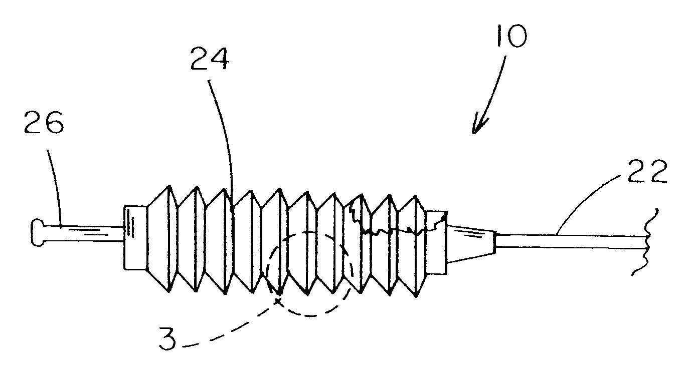
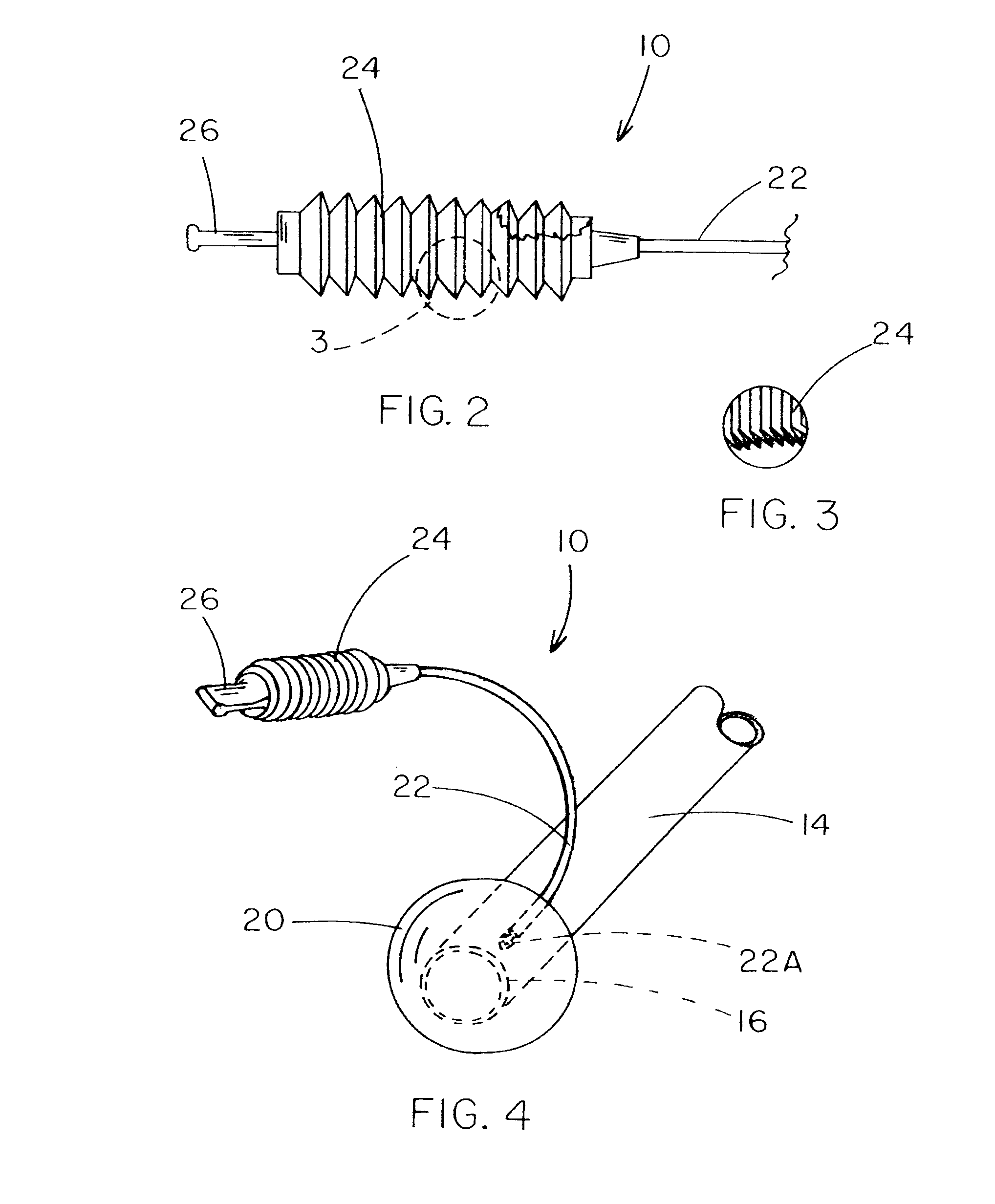
[0041] The following description of practical embodiment(s) is merely exemplary in nature and is in no way intended to limit the invention, its application, or uses. It is common to the various useful embodiments of the present invention that they all include a fixed volume reservoir for inflation fluid and a relatively small diameter elastomeric single lumen tube for transferring inflation fluids; i.e. liquids, gels or gases, in and out of a system retention balloon, such as the spherical-shaped cuff style shown in FIGS. 2-4 or some other shaped cuff, such as a more doughnut shaped version, both of which in use are disposed within a patient's rectum. For clarity of the specification the invention is described here relative to such a bowel management system. However, as previously stated, the new inflation system can also apply to other catheters, such as tracheotomy or intravenous catheters, with balloon retention mechanisms that may or may not have an overall precisely spherical s...


PUM


Abstract

An inflation system (10, 110, 120, 130) for a balloon catheter assembly (12) includes an inflation tube (22), the first end of which is connectable to an inflation fluid reservoir (24, 30) and the second end of which is connectable to and opens into an inflatable cuff (20) on a main catheter (14) of the balloon catheter assembly, to permit the fluid reservoir to be in fluid communication with the cuff. A fluid reservoir is connectable to the inflation tube and is fillable with cuff inflation fluid only to a predetermined, fixed volume, to thereby permit no more than such volume of fluid to be transferred from the reservoir to the cuff during use of the system, to prevent over-inflation of the cuff and thereby avoid potential trauma to the patient.

Description

BACKGROUND OF THE INVENTION [0001] 1. Field of the Invention [0002] The present invention relates, generally, to inflation systems for catheters with balloon-style retention mechanisms, and, more specifically, to a fixed-volume inflation system by which to inflate the retention balloon of an indwelling catheter with a pre-selected fixed volume of inflation media, to thereby prevent over-inflation of the balloon. [0003] 2. Related Art [0004] The present invention is considered for use primarily (but not necessarily exclusively) with or as an improvement to known bowel management devices, such as those presently available and marketed by Zassi Medical Evolutions, Inc and Bowel Management Systems, LLC. These systems are described in U.S. Pat. No. 5,569,216 and pending U.S. application Ser. No. 10 / 225,820, published as US 2004 / 0039348 on Feb. 26, 2004, the entire disclosures of which patent and application are incorporated herein by reference. The present invention can also be incorpora...

Claims


Application Information

Patent Timeline
IPC IPC(8): A61M29/00A61F2/958
CPCA61M25/1018A61M25/10183A61M25/10186A61M25/10185A61M25/10182
Inventor VON DYCK, PETER M.MINASI, JOHN S.SCHNEIDER, JAMES G.MARTINO, NICKBODICKY, RAYMOND O.
Owner HOLLISTER INCORPORAED
Learn More