Video Presentation of Photomultiplier Anode Signal

a video and anode technology, applied in the field of instruments, can solve the problem that the localized response of the photomultiplier tube will not be uniform over the faceplate of the photomultiplier tube, and achieve the effect of reducing the amount of photoemission

Inactive Publication Date: 2006-12-07
BURLE TECH LLC
View PDF1 Cites 4 Cited by
  • Summary
  • Abstract
  • Description
  • Claims
  • Application Information

AI Technical Summary

Benefits of technology

[0012] In the usual mode of operation, there is a close relation between the brightness at any point of the video image so formed according to the above description and the responsivity of the device for radiation incident on the corresponding position of the photocathode or faceplate of the photomultiplier tube. For instance, the brightness of the center of the video image corresponds to the responsivity of the photomultiplier tube for radiation incident at the center of the faceplate. Provided the optical output of the LED array is stable and the light output of each LED element of the array are equal, the video image produced on the television monitor provides a visual image of the areal response uniformity of the photomultiplier tube. For example, a dark spot in the center of the video image would indicate a “dead spot” in the photomultiplier tube response for radiation incident at the center of the faceplate. In general, imperfections in the photocathode may mean that photons striking a particular sub-area of the photocathode exhibit a diminished photoemission relative to surrounding areas of the photocathode. This would be clearly indicated in the video image. As a further example, asymmetries in the arrangement of dynodes relative to the photocathode may cause electrons emitted from some parts of the photocathode to be amplified with a different gain than other parts of the photocathode. Therefore, the localized response of the photomultiplier tube will not be uniform over the faceplate of the photomultiplier tube. This effect would also be indicated in the video image. As a final example, external magnetic fields may skew the electron cascade initiated by photons incident on the photocathode. Thus, the video image provides a real time measurement of the perturbing effects of magnetic fields.

Problems solved by technology

Therefore, the localized response of the photomultiplier tube will not be uniform over the faceplate of the photomultiplier tube.

Method used


Image

  • Video Presentation of Photomultiplier Anode Signal
  • Video Presentation of Photomultiplier Anode Signal
  • Video Presentation of Photomultiplier Anode Signal

Examples


Embodiment Construction

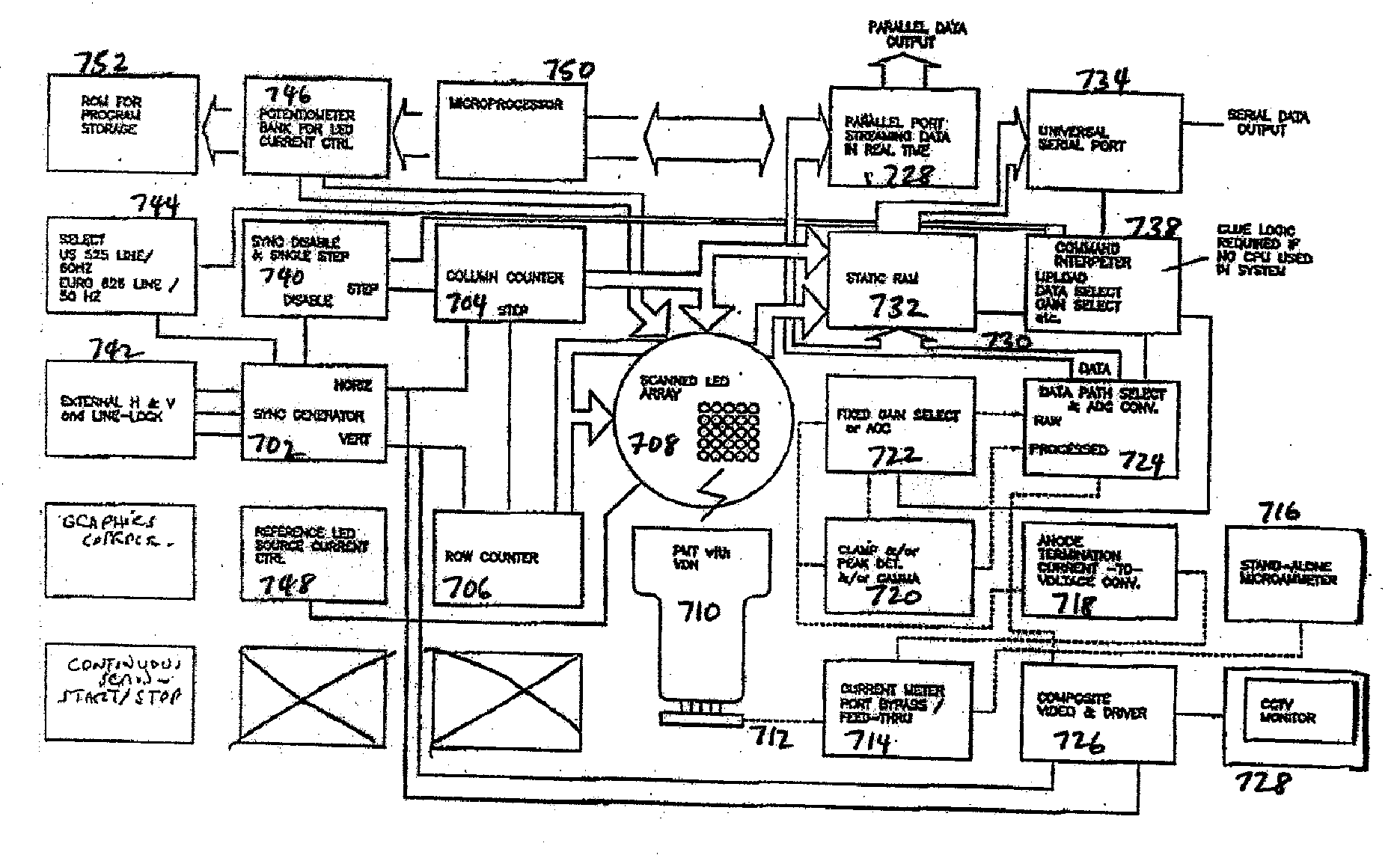
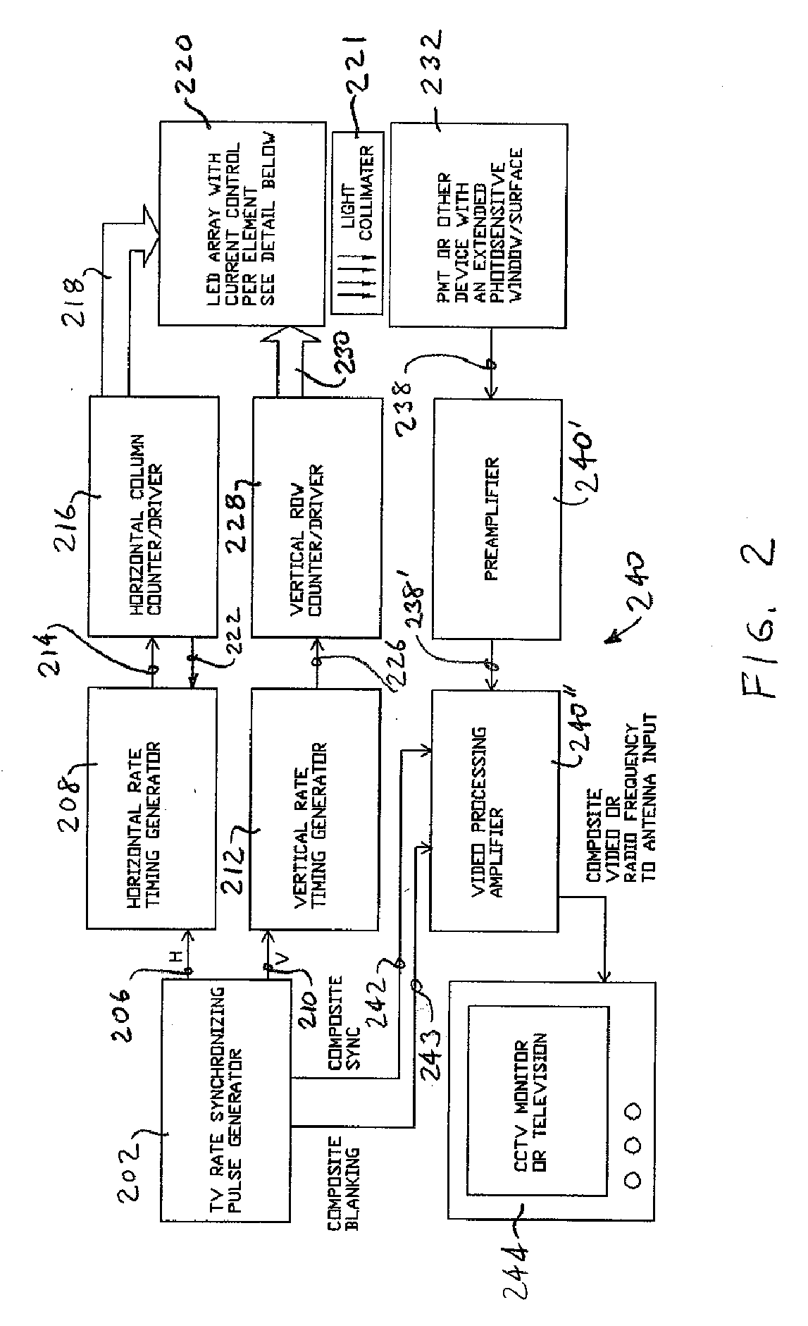
[0022] The present invention provides an apparatus and technique for producing a video image that is representative of the spatial-dependence of the response of a photomultiplier tube to incident radiation. The apparatus and process of the present invention utilize an array of light-emitting diodes (LED's) that are energized in a timing sequence that mimics a cathode ray tube raster scan used in commercial television technology. Specifically, a photomultiplier tube anode signal is modulated by the optical raster scanning of an LED array used to probe the photomultiplier tube. The modulated anode current functions as the camera component of a composite video signal input to a cathode ray tube television monitor. The video image so formed provides a representation of the spatial response uniformity of the photomultiplier tube.

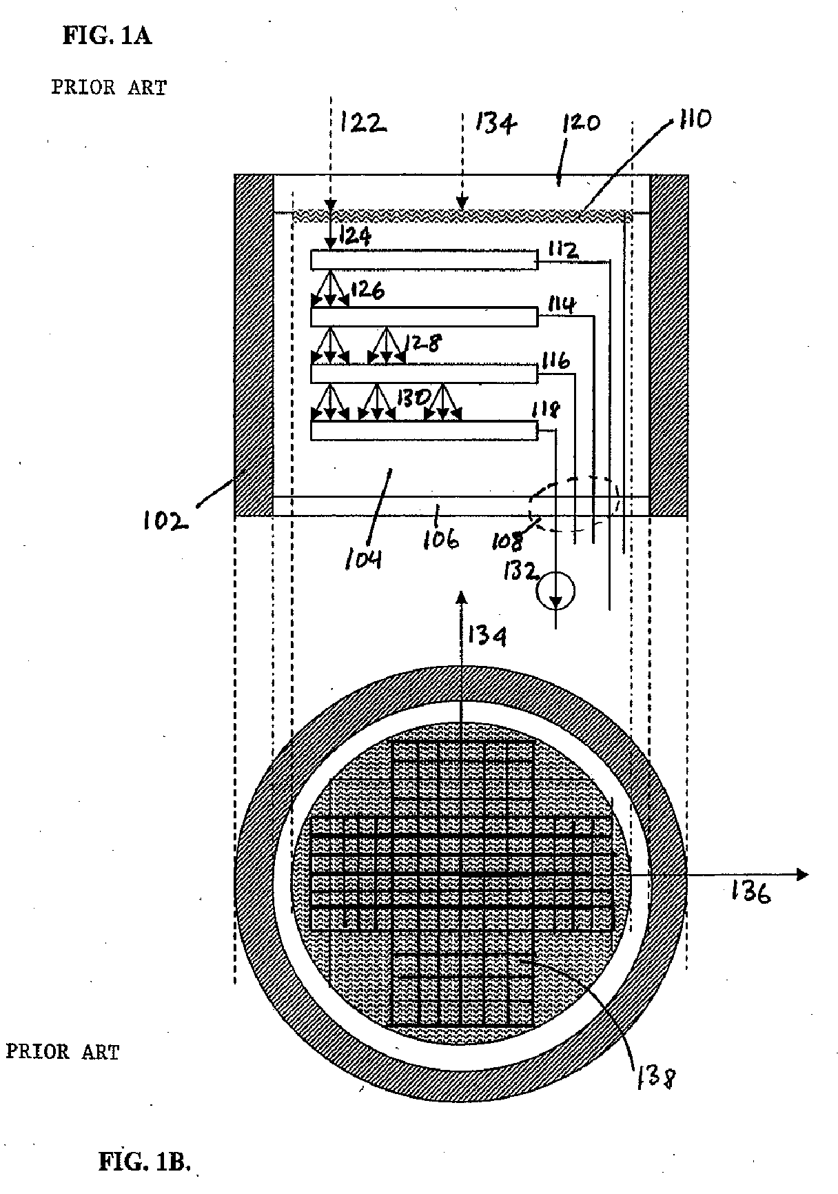
[0023] In general, an array of light-emitting diodes is placed near the faceplate of a photomultiplier tube so that the radiative emission from the light emitti...


PUM


Abstract

An apparatus and method for video imaging the spatial response of radiation-responsive devices, such as photomultiplier tubes. The apparatus probes the device under-test with an array of radiation emitting elements, such as light-emitting diodes, programmed with a scanning sequence such that the device under-test output response, e.g., the anode current of a photomultiplier tube, may serve as a video signal to a video display device such as a television or monitor. A video image so produced provides a map of the spatial response of the radiation-responsive device which may indicate perturbances, flaws, and inhomogeneities in the spatial responsivity of the device.

Description

FIELD OF THE INVENTION [0001] This invention concerns instrumentation to perform diagnostics on photomultiplier tubes and other optical detection devices. More particularly, the invention relates to an apparatus that creates a video image that is representative of the variations in localized responsivity and gain of the photosensitive elements and associated electrodes of a photomultiplier tube. The invention can also be used to assess spatial variations in responsivity of other types of devices such as image intensifiers, semiconductor detectors, and solar cells. BACKGROUND OF THE INVENTION [0002] Photomultiplier tubes are vacuum tube optical detection devices that generate a real-time electrical signal in response to incident radiation. Ideally, the magnitude of the electrical response is proportional to the intensity of the incident radiation. Photomultiplier tubes provide high gain, fast response, and good sensitivity due to their inherent amplification and low-noise characteris...

Claims


Application Information

Patent Timeline
Patent Type & Authority Applications(United States)
IPC IPC(8): H01J40/14
CPCG01J1/08
Inventor THOMPSON, ROBERT C.
Owner BURLE TECH LLC
Why Eureka
Try Eureka