Combined laser source having deflection member

a laser source and deflection member technology, applied in the field of combined laser sources, can solve the problems of inability to increase the numerical aperture (na) the inability to increase the focal length of the condensing lens, and the inability to reduce the core diameter of the optical fiber, so as to achieve the effect of reducing the cost, maximizing the utilization efficiency of the optical condensing system, and high intensity

Inactive Publication Date: 2006-12-07
ADTEC ENG +1
View PDF5 Cites 42 Cited by
  • Summary
  • Abstract
  • Description
  • Claims
  • Application Information

AI Technical Summary

Benefits of technology

[0017] The object of the present invention is to provide a combined laser source which can be produced at low cost and emits a high-intensity laser beam.
[0044] (j) In the case where the combined laser source according to the present invention has the aforementioned additional feature (xii), it is possible to guarantee a sufficient focal depth for exposure of highly fine images, and expose highly sharp images.

Problems solved by technology

Therefore, it is impossible to increase the numerical aperture (NA) of the optical fiber.
Nevertheless, the increase in the sizes of the images of the emission points at the light-condensing position is incompatible with the reduction in the core diameter of the optical fiber.
Therefore, it is unpreferable to increase the focal length of the condensing lens.
In particular, the magnification power is an unignorable factor in the case where the semiconductor lasers have broad emission areas, although the emission points of the single-mode semiconductor lasers are small.
When the position adjustment is inaccurate, and the laser beams deviate from the core of the optical fiber, loss occurs in the amount of light, so that the output intensity cannot be increased.
Further, since the operation for the position adjustment is required to be repeated the number of times corresponding to the number of the semiconductor lasers, the requirement of the high precision in the position adjustment of the semiconductor lasers and the collimator lenses is a serious cost-increasing factor.
However, if the semiconductor lasers and the collimator lenses are too closely arranged, it is impossible to allow sufficient space to mount the semiconductor lasers and the collimator lenses.
Therefore, the close arrangement of the semiconductor lasers and the collimator lenses imposes constraints on the constituents per se and adjustment of the constituents.
Thus, the close arrangement of the semiconductor lasers and the collimator lenses is disadvantageous in terms of the cost of the components, devices for adjustment, and the man-hours needed for adjustment, and increases the total cost.
However, the operation of mounting the chips increases man-hours needed for quality assurance.
In addition, since the semiconductor-laser array and the collimator-lens array are custom-built, the cost of a high-precision mounting device adapted for the custom-built components is high, so that it is a heavy burden to recover the cost of the mounting device.
Therefore, it is almost impossible to reduce the cost by using the above method.
Further, in the conventional combined laser source in which a number of semiconductor-laser chips area arranged on a heat block, the entire combined laser source is required to be sealed, and the yield rate is low, since the entire combined laser source becomes a defective even when only one of the chips or the lenses is defective.
Thus, the total cost of the conventional combined laser source is high.
However, the sizes of the sealed packages of the conventional semiconductor lasers are large, so that the gaps between the light-emission points of the semiconductor lasers increase, and the amount of light per unit area in a plane in the condensing lens decreases.

Method used


Image

  • Combined laser source having deflection member
  • Combined laser source having deflection member
  • Combined laser source having deflection member

Examples


first embodiment

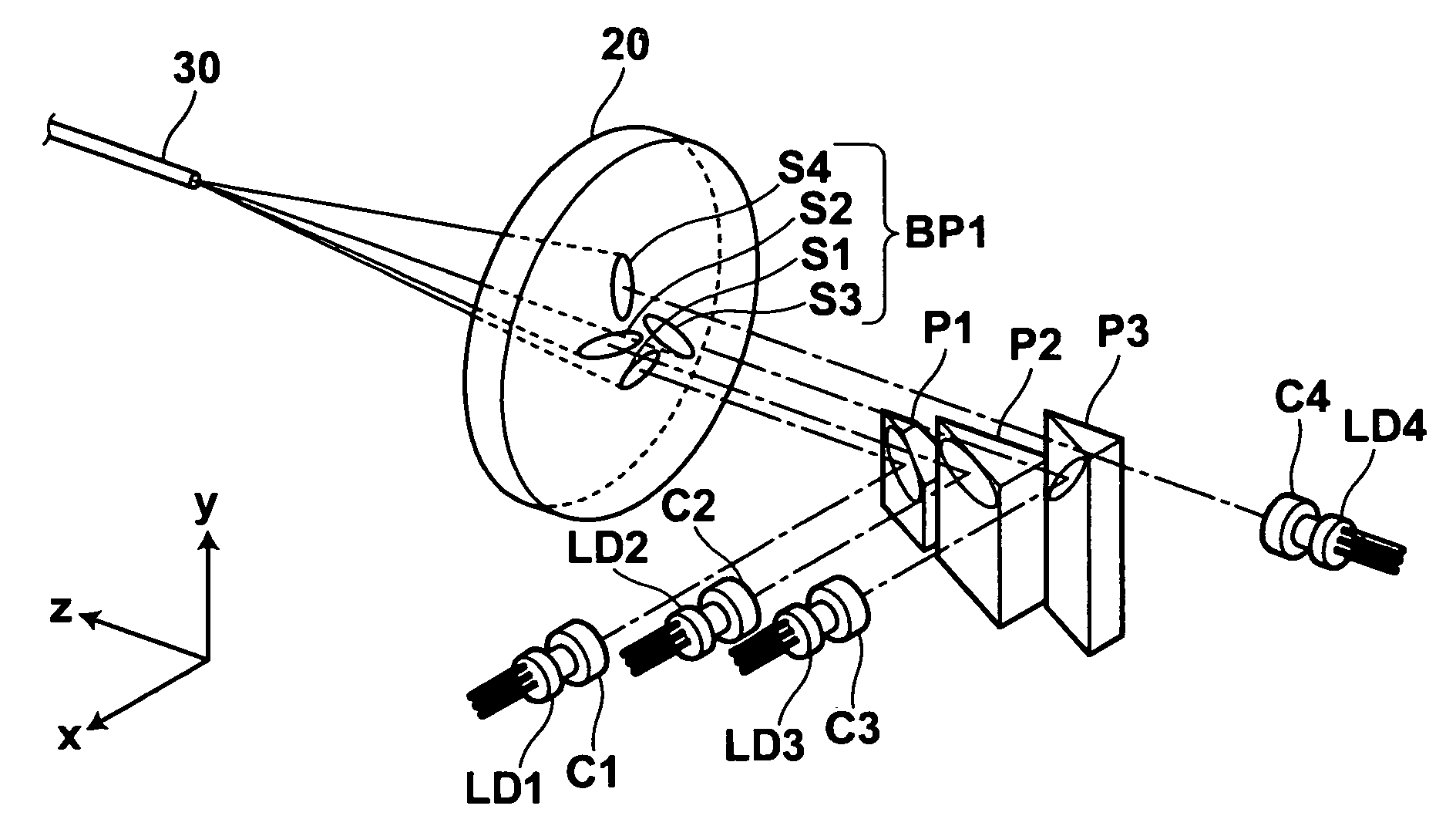
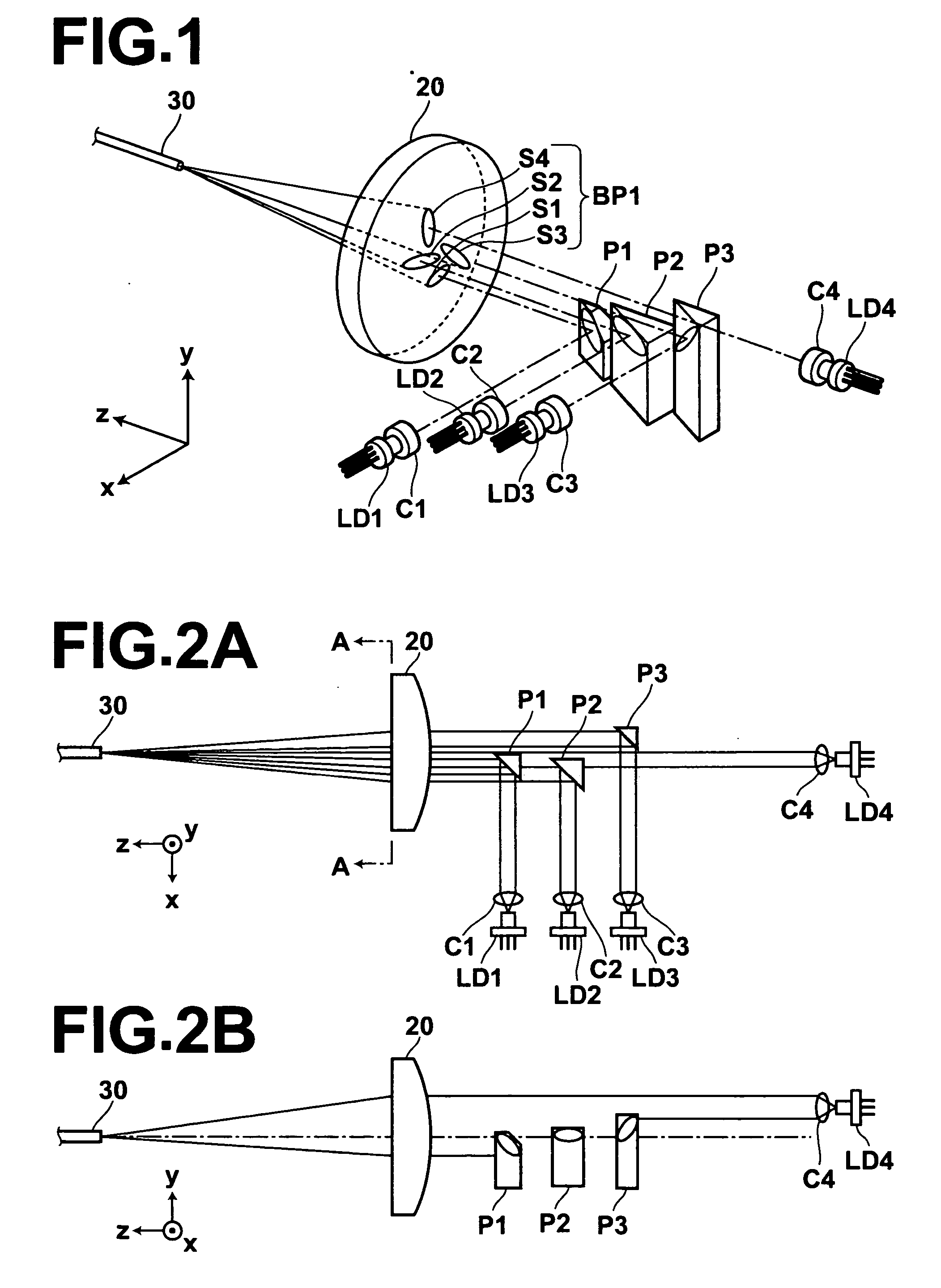
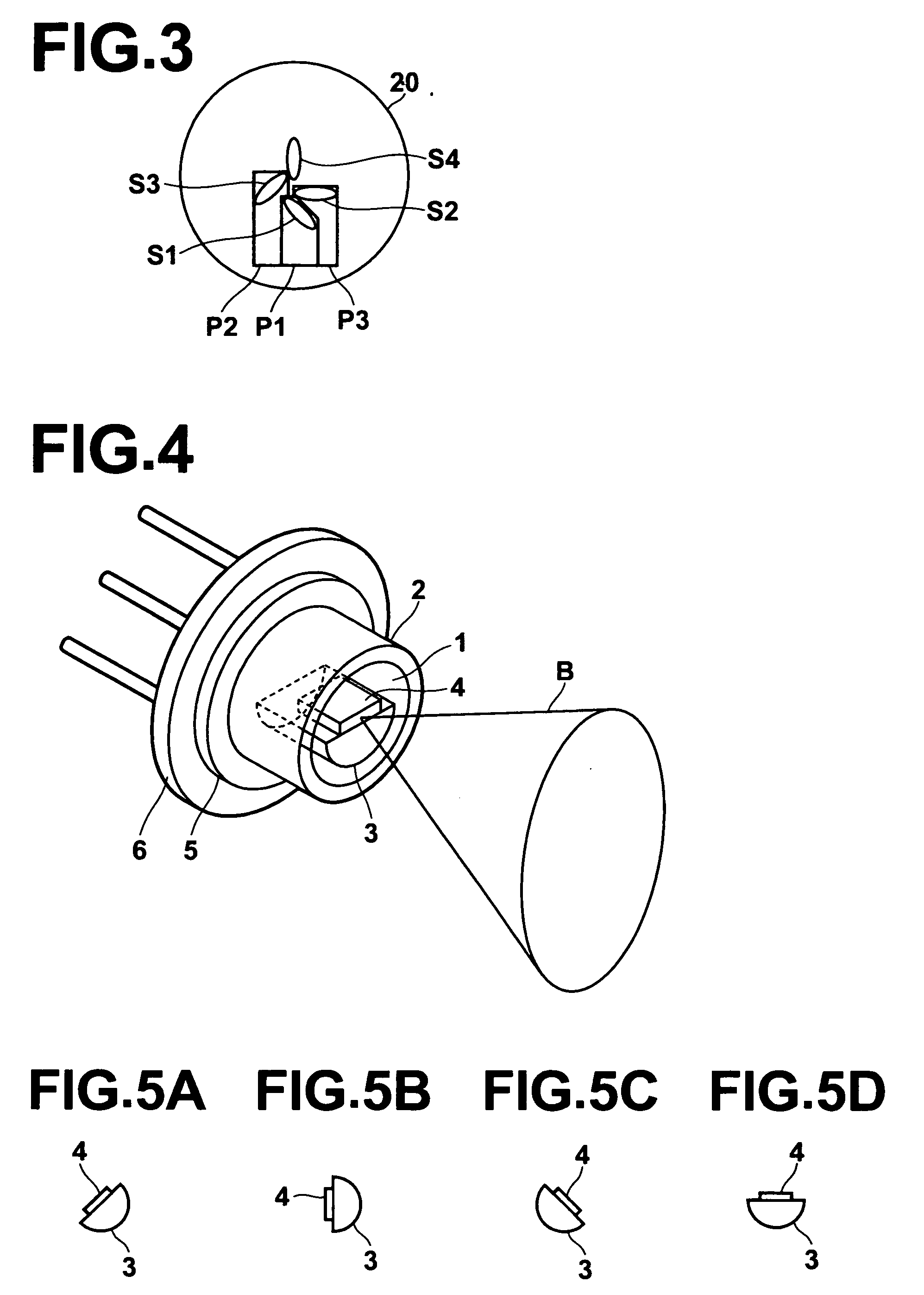
[0072] First, a combined laser source according to the first embodiment of the present invention is explained below with reference to FIGS. 1, 2A, 2B, and 3. FIGS. 1, 2A, and 2B are respectively perspective, plan, and side views of the combined laser source according to the first embodiment, and FIG. 3 is a front view of a portion, containing a condensing lens and deflection members, of the combined laser source according to the first embodiment, viewed from the position A-A indicated in FIG. 2A. In FIGS. 1, 2A, and 2B, the z direction corresponds to the direction of the optical axis of the condensing lens, and x and y directions are perpendicular to the z direction. Specifically, FIG. 2A is a view from the y direction, and FIG. 2B is a view from the x direction. In addition, semiconductor lasers and collimator lenses are not shown in FIG. 2B.

[0073] The combined laser source according to the first embodiment comprises four semiconductor lasers LD1, LD2, LD3, and LD4, four collimato...

second embodiment

[0102] Hereinbelow, a combined laser source according to the second embodiment of the present invention is explained below with reference to FIGS. 7, 8A, and 8B. FIGS. 7, 8A, and 8B are respectively perspective, plan, and side views of the combined laser source according to the second embodiment. In FIGS. 7, 8A, and 8B, the z direction corresponds to the direction of the optical axis of the condensing lens 20, and x and y directions are perpendicular to the z direction. Specifically, FIG. 8A is a view from the y direction, and FIG. 8B is a view from the x direction. In addition, semiconductor lasers and collimator lenses are not shown in FIG. 8B.

[0103] The combined laser source according to the second embodiment comprises eight semiconductor lasers LD1 through LD8, eight collimator lenses C1 through C8, eight deflection members P21 through P28, a condensing lens 20, and an optical fiber 30.

[0104] The eight semiconductor lasers LD1 through LD8 emit eight divergent laser beams. The ...

third embodiment

[0114] Hereinbelow, a combined laser source according to the third embodiment of the present invention is explained below with reference to FIGS. 9, 10A, and 10B. FIGS. 9, 10A, and 10B are respectively perspective, plan, and side views of the combined laser source according to the third embodiment. In FIGS. 9, 10A, and 10B, the z direction corresponds to the direction of the optical axis of the condensing lens 20, and x and y directions are perpendicular to the z direction. Specifically, FIG. 10A is a view from the y direction, and FIG. 10B is a view from the x direction. In addition, semiconductor lasers and collimator lenses are not shown in FIG. 10B.

[0115] The combined laser source according to the third embodiment comprises seven semiconductor lasers LD1 through LD7, seven collimator lenses C1 through C7, seven deflection members P31 through P37, a condensing lens 20, and an optical fiber 30.

[0116] The seven semiconductor lasers LD1 through LD7 emit seven divergent laser beams...


PUM


Abstract

A combined laser source includes: a plurality of semiconductor lasers which contain emission elements emitting a plurality of laser beams and being separately and hermetically sealed; a plurality of collimator lenses which collimate the plurality of laser beams emitted from the emission elements of the plurality of semiconductor lasers; an optical condensing system which receives, condenses, and optically combines the plurality of laser beams collimated by the plurality of collimator lenses; and one or more deflection members which are arranged between the optical condensing system and one or more of the plurality of collimator lenses, and deflect one or more of the plurality of laser beams collimated by the one or more of the plurality of collimator lenses so that the one or more of the plurality of laser beams propagate parallel to an optical axis of the optical condensing system.

Description

BACKGROUND OF THE INVENTION [0001] 1. Field of the Invention [0002] The present invention relates to a combined laser source which optically combines laser beams emitted from a plurality of semiconductor lasers by using an optical condensing system. [0003] 2. Description of the Related Art [0004] Conventionally, the combined laser sources which condense and optically combine a plurality of laser beams emitted from a plurality of laser-light sources by using an optical condensing system are known as high-power laser-light sources which can be used in exposure systems and the like. FIG. 25 is a plan view of an example of such a combined laser source. In the combined laser source illustrated in FIG. 25, the laser beams B1 to B7 emitted from the seven semiconductor-laser chips L1 to L7, which are aligned along a line and fixed on a heat block 10, are respectively collimated by the seven collimator lenses 11 to 17 and are condensed by the condensing lens 21 so that the collimated and con...

Claims


Application Information

Patent Timeline
Patent Type & Authority Applications(United States)
IPC IPC(8): G02B7/02
CPCG02B6/4214G02B27/0966G02B19/0028G02B19/0057G02B27/0972
Inventor MINO, SATOSHISONODA, SHINICHIRO
Owner ADTEC ENG
Why Eureka
Try Eureka