Superconducting FCL using a combined inducted magnetic field trigger and shunt coil

a superconducting and magnetic field technology, applied in the direction of emergency protective circuit arrangements, emergency protective arrangements for limiting excess voltage/current, electrical equipment, etc., can solve the problem of a part of the fault current being diverted, and achieve the effect of improving the reliability of the device, less complexity, and adding to the complexity of the devi

Inactive Publication Date: 2006-12-07
SUPERPOWER INC
View PDF6 Cites 9 Cited by
  • Summary
  • Abstract
  • Description
  • Claims
  • Application Information

AI Technical Summary

Benefits of technology

[0013] As the need for higher power and higher voltage applications of Fault Current Limiters increases, designing a device with less complexity and yet using magnetic field for triggering becomes a challenge. Optimizing fault current limiter design with fewer overall components is important to design a reliable high voltage device at a transmission system level. As the power and voltage requirement increases, the number of components (superconductors and magnetic field coils) increase, which adds to the complexity of the device. Reducing the number of parts is one of the ways to improve reliability of the device. There therefore exists a need for a simplified design with improved reliability in a SCFLC device for transmission system applications.

Problems solved by technology

Once there is a system fault, the current surge will exceed the critical current level of the superconductor element and cause it to quench very quickly, thus generating a sufficiently large voltage drop across the shunt coil which results in part of the fault current being diverted into the trigger / shunt coil.

Method used


Image

  • Superconducting FCL using a combined inducted magnetic field trigger and shunt coil
  • Superconducting FCL using a combined inducted magnetic field trigger and shunt coil
  • Superconducting FCL using a combined inducted magnetic field trigger and shunt coil

Examples


Embodiment Construction

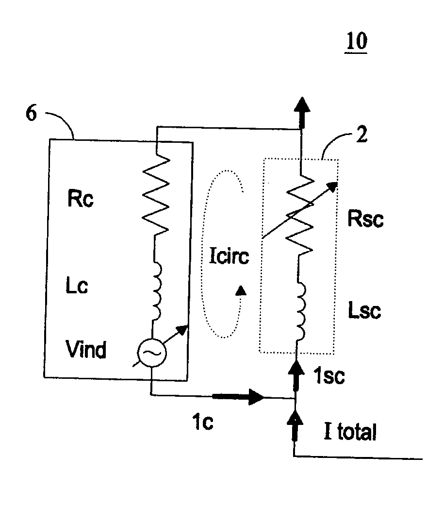
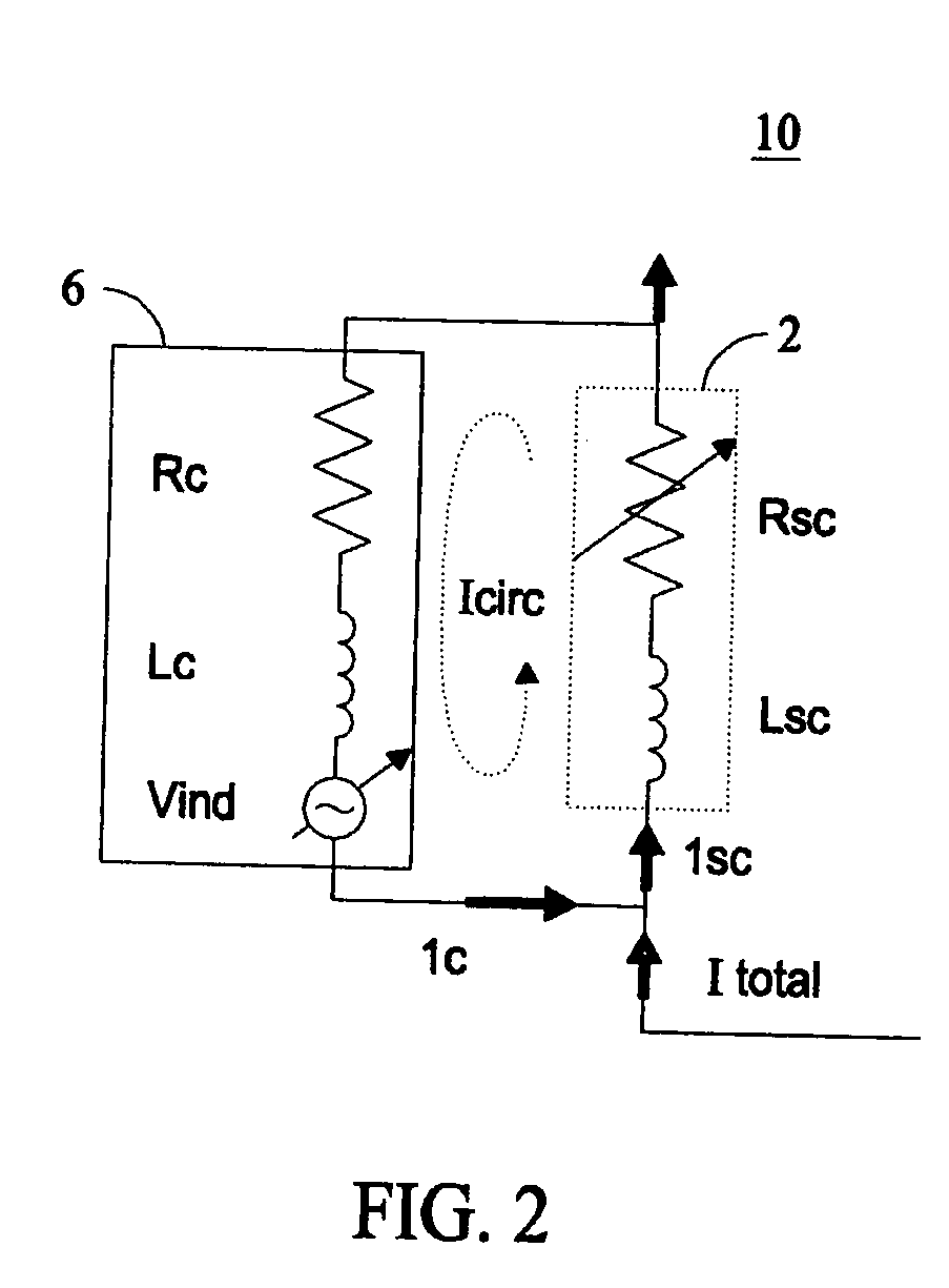
[0029] U.S. patent application Ser. No. 11 / 097,560, entitled “Self-Triggering Superconducting Fault Current Limiter”, filed on Apr. 2, 2005, assigned to the assignee of the present invention, is herein incorporated by reference in its entirety. This application describes a FCL having a shunt and a trigger coil coupled in parallel with a superconductor which design is modular and scalable that functions as a “variable impedance” using components made of superconducting as well as conventional electrically conductive materials. U.S. Pat. No. 6,809,910, entitled “Method and Apparatus To Trigger Superconductors In Current Limiting Devices”, issued on Oct. 26, 2004, assigned to the assignee of the present invention, is herein incorporated by reference in its entirety. This patent describes a FCL having a shunt and a trigger coil and provides details about the trigger coils and the triggering method and mechanism.

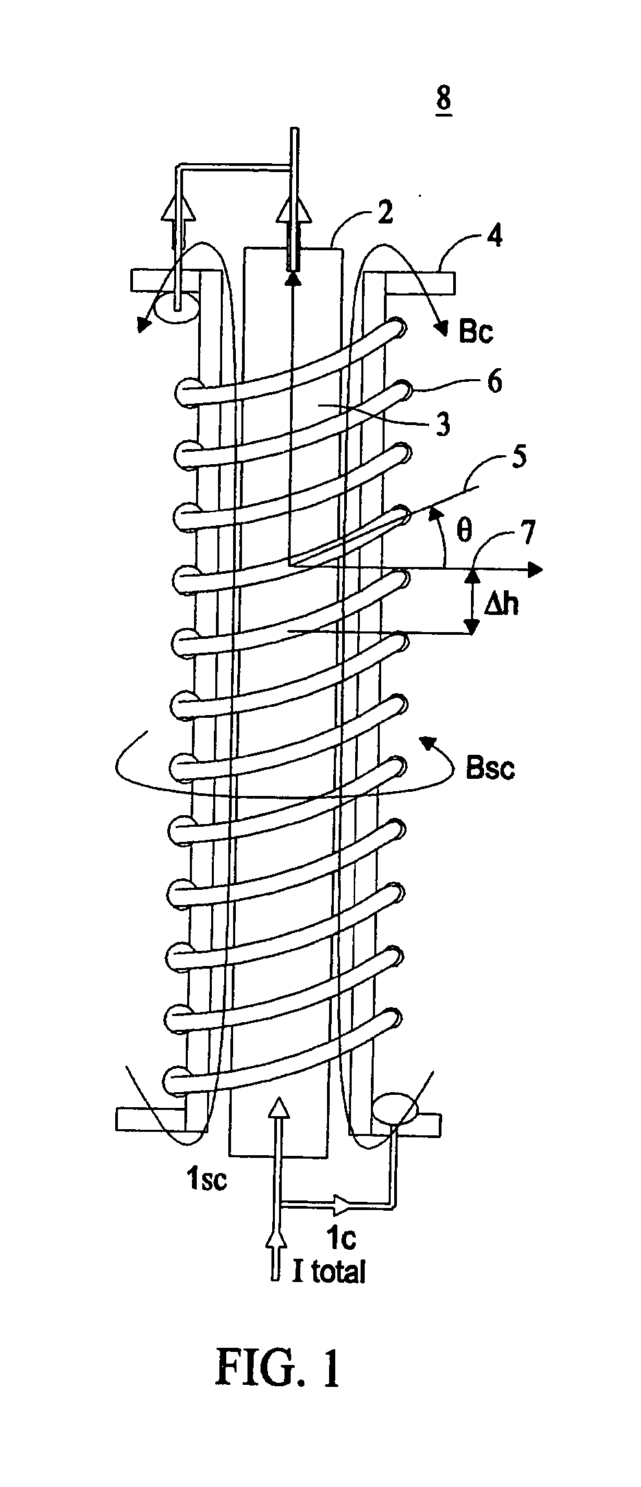
[0030]FIG. 1 illustrates a simplified physical layout of a superconducting ...


PUM


Abstract

A single trigger/shunt coil is utilized for combined induced magnetic field triggering and shunt impedance. The single coil connected in parallel with the high temperature superconducting element, is designed to generate a circulating current in the parallel circuit during normal operation to aid triggering the high temperature superconducting element to quench in the event of a fault. The circulating current is generated by an induced voltage in the coil, when the system current flows through the high temperature superconducting element.

Description

CROSS REFERENCE TO RELATED APPLICATIONS [0001] This U.S. non-provisional application claims the benefit of U.S. provisional Patent Application, Ser. No. 60 / 686,378 entitled “Superconducting FCL Using A Combined Inducted Magnetic Field Trigger and Shunt Coil,” filed on Jun. 1, 2005, having at least one co-inventor in common with this application.[0002] The U.S. government has a paid-up license in this invention and the right in limited circumstances to require to the patent owner to license others on reasonable terms as provided for in the terms of Contract No. DE-FC36-03GO13033 awarded by the Department of Energy.BACKGROUND [0003] The invention relates generally to a current limiter and more specifically to a superconducting fault current limiter. [0004] Current limiting devices are critical in electric power transmission and distribution systems. For various reasons such as lightening strikes, short circuit conditions can develop in various sections of a power grid causing sharp su...

Claims


Application Information

Patent Timeline
Patent Type & Authority Applications(United States)
IPC IPC(8): H02H7/00
CPCH01L39/20Y02E40/69H02H9/023Y02E40/60H10N60/355
Inventor TEKLETSADIK, KASEGN D.
Owner SUPERPOWER INC
Why Eureka
Try Eureka