
Bone fixation plate with self-locking screws

a bone screw and self-locking technology, applied in the field of orthopedic bone fixation devices, can solve the problem of the bone screws not being able to pull the bone plate against the vertebral body, and achieve the effect of high strength, improved bone growth assessment, and high strength

Inactive Publication Date: 2006-12-07
AMEDICA A DELAWARE
View PDF15 Cites 312 Cited by
  • Summary
  • Abstract
  • Description
  • Claims
  • Application Information

AI Technical Summary

Benefits of technology

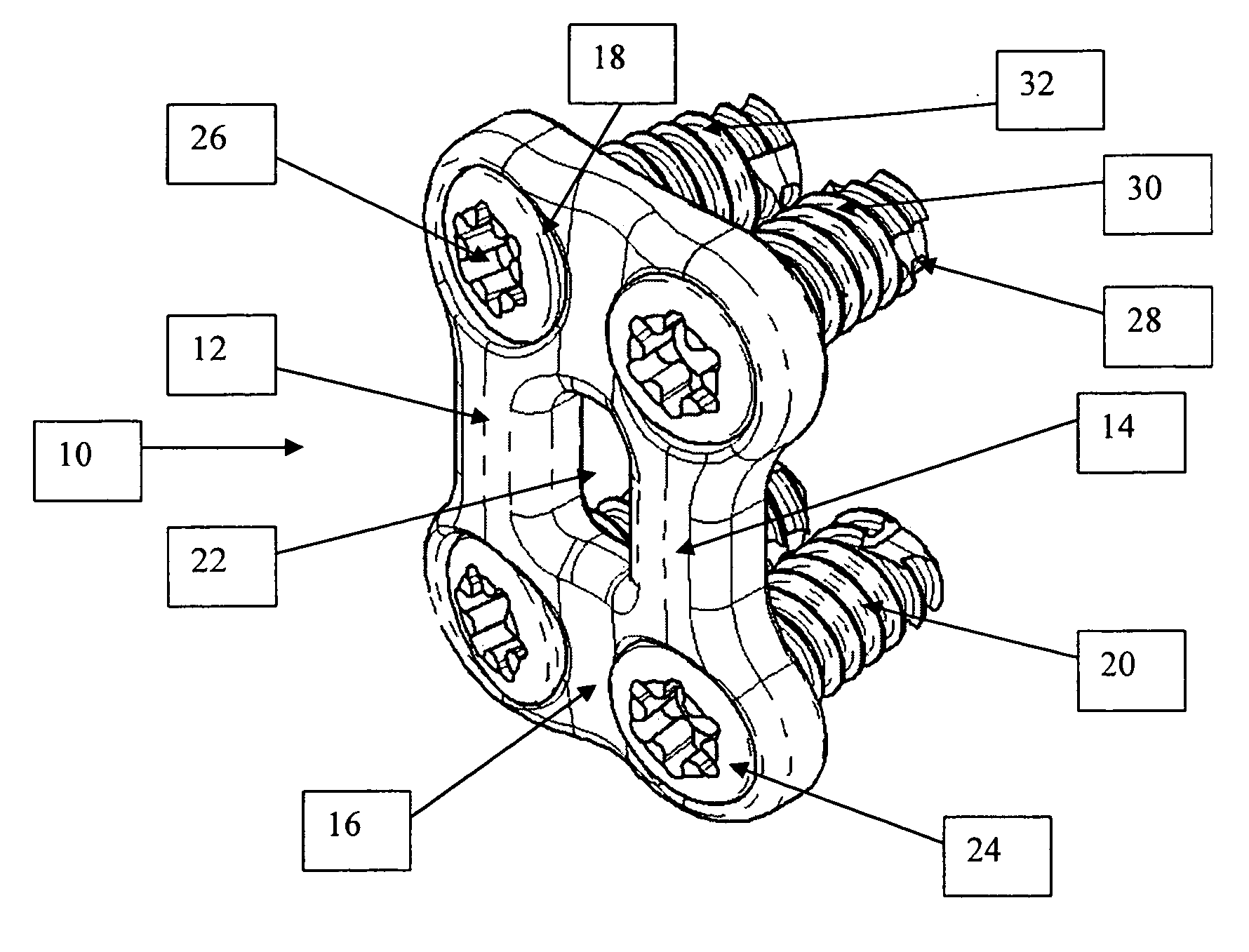
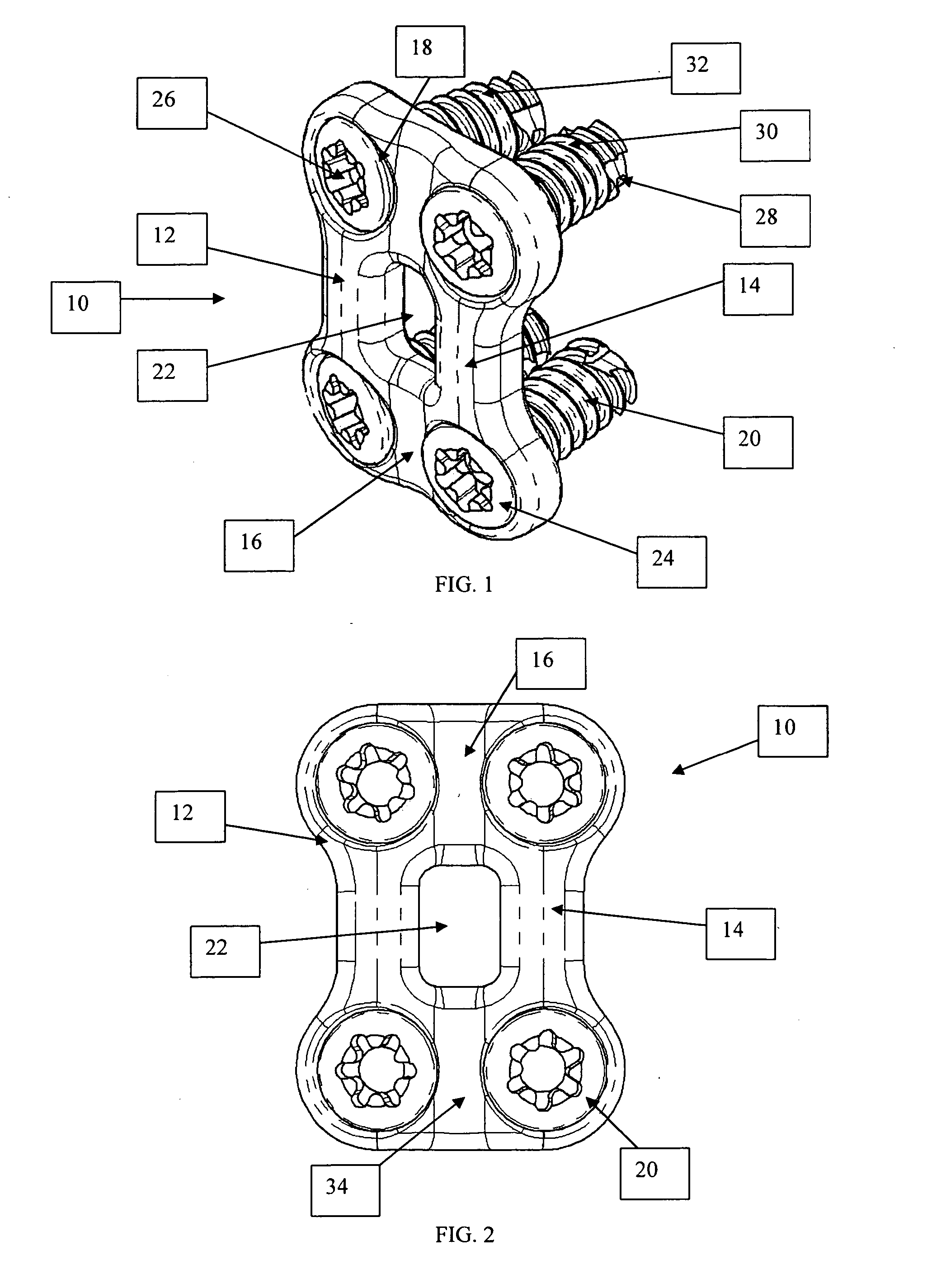
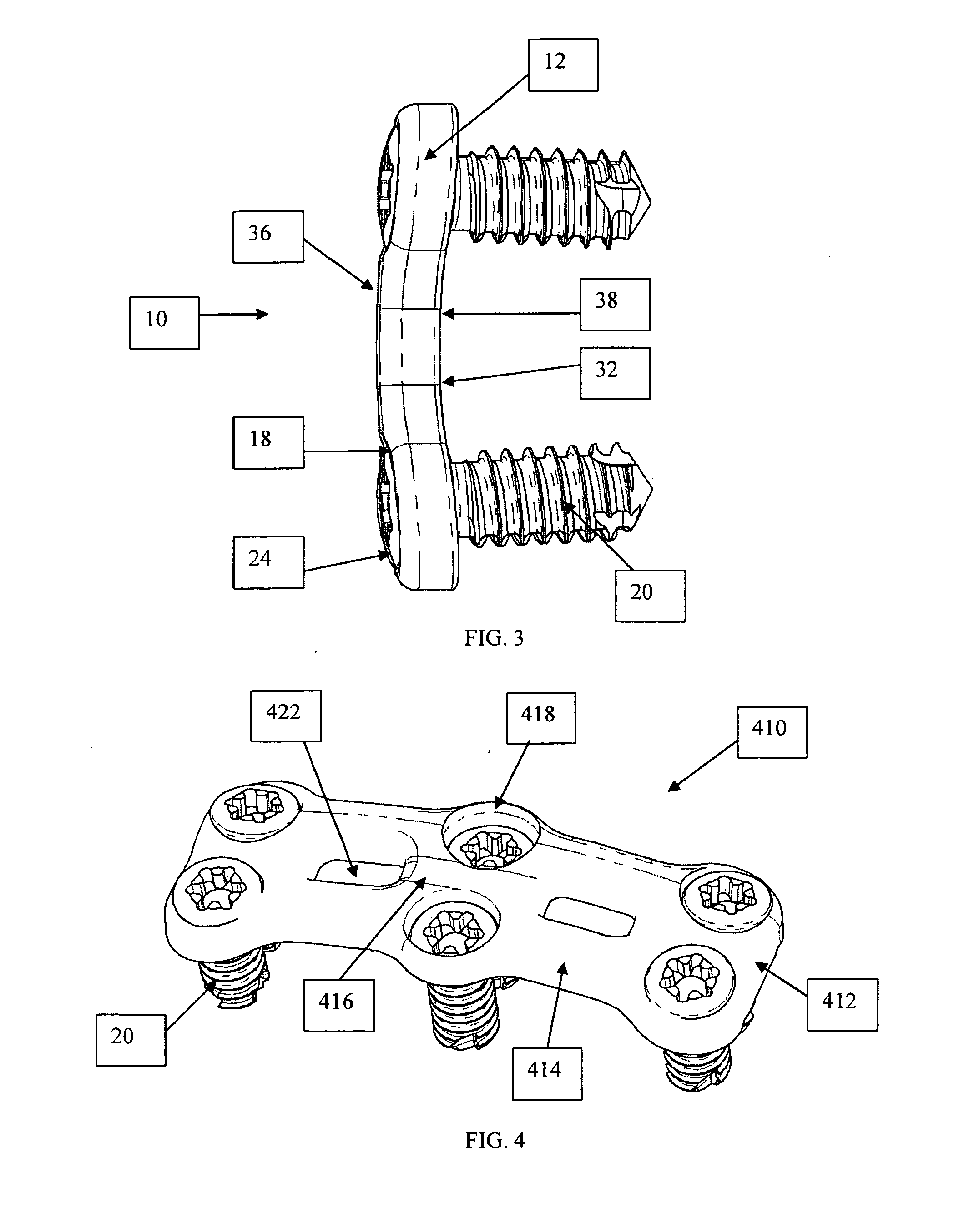
[0018] In one preferred embodiment of the disclosed device, each bone screw fastener has a ‘collar’ of flexible tangs encircling a threaded screw shaft or shank. The flexible tangs are positioned between the screw head and the screw threads. As the flexible tangs pass through the narrow portion of the associated bone plate aperture, they flex or bend in order to pass. Once through the associate aperture, the flexible tangs spring or flex back substantially to their original nondeformed position, thus preventing the bone screw from exiting or backing out of the bone plate. The flexible tangs are desirably positioned far enough away from the screw head to allow some relative movement between the bone screw and the bone plate.
[0019] In a second preferred embodiment of the device, the bone screw fastener features two thread forms formed along its shaft or shank. A first thread form consists of threads used to interface with or engage vertebral bone upon device implantation. This first thread form is located at a distal end of the screw shaft, opposite the screw head. A second thread form, located more proximal to the screw head, has a greater or larger major diameter than the first thread form. This second thread form is designed to engage a similar or mating female thread form formed in the associated aperture of the bone plate. With this construction, the female thread form on the bone plate is sized to allows the first thread form on the bone screw to pass relatively freely, while threadably engaging the larger second thread form proximal to the bone screw head. The first and second bone screw thread forms are of generally the same pitch to allow continuous advancing of the bone screw, i.e., thread-in engagement of the first thread form with patient bone concurrently with thread-in engagement of the second thread form with the bone plate female thread. At this point, the bone screw is captured by the bone plate. In the preferred form, the second thread form on the bone screw is spaced sufficiently from the associated head, so permit the second thread form to be advanced past the threaded bone plate aperture for disengagement of the second thread form from the bone plate. This construction enables the bone screw to articulate within the associated aperture of the bone plate, allowing for various bone screw trajectories as well as settling between the bone plate and the adjacent patient bone structure such as spinal vertebrae. A further value of the second thread form disengaging from the bone plate is that it allows the bone screws to have a lag screw effect. If the threads do not disengage, it is impossible for the bone screws to pull the bone plate against the vertebral bodies.
[0020] This second embodiment, with the two thread forms on the bone screw, also allows for constrained screws to be placed. Utilizing the same bone plate, both semi-constrained and constrained screws may be implanted. By making the second thread form on the bone screw a more intimate fit with the female threads within the associated bone plate aperture, the bone screw becomes constrained within the aperture. This can be useful if the surgeon needs only superior bone screws to articulate, but also needs inferior bone screws to be constrained.
[0021] Additionally, both of the previous embodiments are able to be manufactured from a variety of materials. One such preferred material is a high strength ceramic. These high strength ceramics are both radiolucent and MRI compatible. They allow the surgeons to better assess the new bone growth in and around the plate using standard techniques. The bone plates, as well as the bone screws, are able to be manufactured from these ceramics. Another preferred material is high strength polymer. Although not as strong as the ceramics, the polymers offer similar benefits of radiolucency and MRI compatibility.

Problems solved by technology

If the threads do not disengage, it is impossible for the bone screws to pull the bone plate against the vertebral bodies.

Method used


Image

  • Bone fixation plate with self-locking screws
  • Bone fixation plate with self-locking screws
  • Bone fixation plate with self-locking screws

Examples


Embodiment Construction

[0036] For the purposes of promoting an understanding of the principles in accordance with the invention, reference will now be made to the embodiments illustrated in the drawings and specific language will be used to describe the same. It will nevertheless be understood that no limitation of the scope of the invention is thereby intended. Any alterations and further modifications of the inventive features illustrated herein, and any additional applications of the principles of the invention as illustrated herein, which would normally occur to one skilled in the relevant art and having possession of this disclosure, are to be considered within the scope of the invention claimed.

[0037] Before the present device and methods for implantation of said device are disclosed and described, it is to be understood that this invention is not limited to the particular configurations, process steps, and materials disclosed herein as such configurations, process steps, and materials may vary som...


PUM


Abstract

A dynamic bone fixation plate assembly includes a bone plate with at least one fastener-receiving aperture, and at least one self-locking fastener. Each fastener includes a threaded shaft or shank for secure engagement with patient bone, and a head for engaging the bone plate in a manner providing a low profile orthopedic device. The fastener shank includes features lock the fastener to the bone plate to prevent the fastener from backing out of the bone plate while still allowing rotational movement between the fastener and the plate. Utilizing the features of the present invention, the bone plate controllably subsides and settles into a position of stability.

Description

BACKGROUND OF THE INVENTION [0001] The present invention relates generally to orthopedic bone fixation devices for stabilizing a plurality of bone segments, and more particularly, but not necessarily entirely, to a bone plate and a bone screw assembly for stabilizing the cervical spine and blocking movement of grafts, and otherwise maintaining the cervical vertebrae in a desired relationship. [0002] The spine is a flexible, multi-segmented column that supports the upright posture in a human while providing mobility to the axial skeleton. The spine serves the dual functions of encasing and protecting vital neural elements while providing structural support for the body by transmitting the weight of the body through the pelvis to the lower extremities. The cervical spine, because of the orientation of its facets and due to the lack of supporting structures, exhibits a wide range of motion. The thoracic and lumbar regions of the spine also have a significant range of motion, but are li...

Claims


Application Information

Patent Timeline
Patent Type & Authority Applications(United States)
IPC IPC(8): A61F2/30
CPCA61B17/8057A61B17/8052
Inventor BERRY, BRET M.
Owner AMEDICA A DELAWARE
Learn More