Liquid discharge head manufacturing method, and liquid discharge head obtained using this method

a liquid discharge head and manufacturing method technology, applied in the direction of instruments, photomechanical devices, coatings, etc., can solve the problems of new technical problems and deterioration of printed images

Inactive Publication Date: 2006-12-14
CANON KK
View PDF84 Cites 44 Cited by
  • Summary
  • Abstract
  • Description
  • Claims
  • Application Information

AI Technical Summary

Benefits of technology

[0011] While taking the above shortcoming into account, the objective of the present invention is to provide a method for manufacturing a liquid discharge head whereby a dissolvable and removable solid layer, which is a mold for defining a flow path pattern, and a discharge port formation material layer, which coats the solid layer, are employed, and whereby a scum does not occur at the interface whereat these layers make direct contact, and small droplets (including extremely small droplets) are accurately discharged at the discharge ports and a liquid ejection head obtained using this manufacturing method.

Problems solved by technology

When this ink jet recording head was manufactured, however, using the methods described in the above-described patent publications, new technical problems were found.
Specifically, as one phenomenon, a scum occurs at the interface between a removable resin and a discharge port formation material used for forming ink discharge ports, and the direction in which ink droplets are ejected from the discharge port faces is bent, so that a printed image is deteriorated.

Method used


Image

  • Liquid discharge head manufacturing method, and liquid discharge head obtained using this method
  • Liquid discharge head manufacturing method, and liquid discharge head obtained using this method
  • Liquid discharge head manufacturing method, and liquid discharge head obtained using this method

Examples


first embodiment

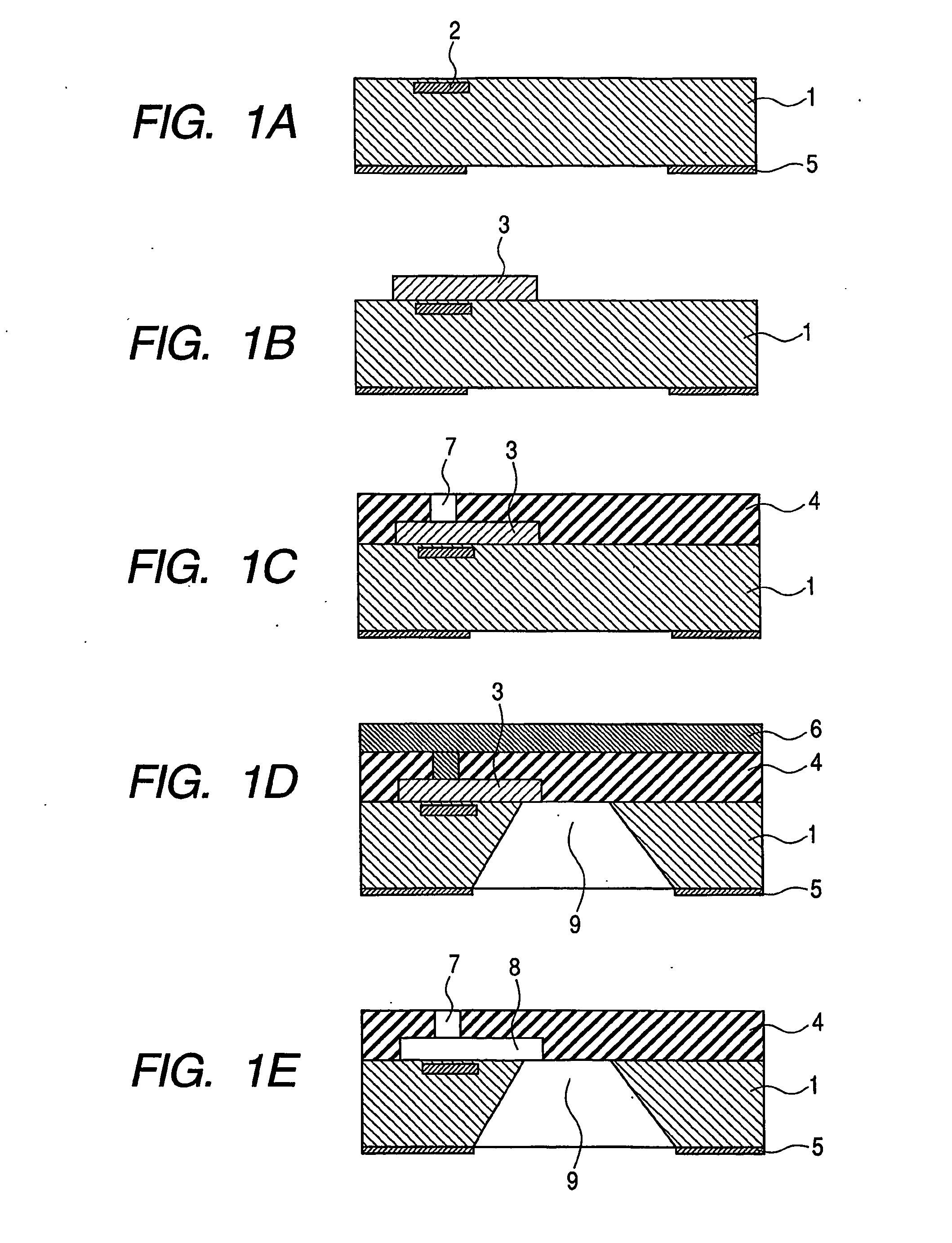
[0055] FIGS. IA to IE are schematic cross-sectional views showing the processing for a method according to a first embodiment of this invention for manufacturing a liquid discharge head. The method for manufacturing a liquid discharge head according to this embodiment will now be explained while referring to FIGS. IA to IE.

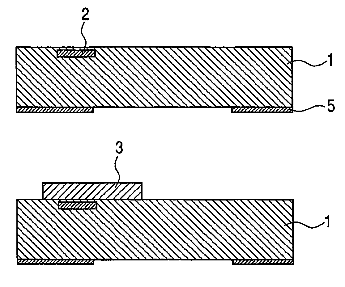
[0056] In FIG. IA, heat generation devices 2, which are liquid discharge energy generating elements, transistors, which independently drive the heat generation devices, and a circuit (not shown), which processes a data signal, for example, are mounted on a silicon substrate 1, and are electrically connected by wiring. A nitride film 5 is used as a mask for forming an ink supply port 9 that will be described later.

[0057] Then, as shown in FIG. IB, a positive resist layer 3 is coated on the silicon substrate 1 as a dissolvable and removable solid layer, and baked. A general solvent coating method, such as spin coating or bar coating, can be employed for the coatin...

second embodiment

[0068]FIGS. 4A to 4F are cross-sectional views for explaining example solid layer formation processing that can be employed for the present invention. A second embodiment of this invention differs from the first embodiment in that a laminated structure, for which a plurality of materials are used, is employed for the solid layer.

[0069] First, the solid layer formation processing that can be employed for this invention will be described while referring to FIGS. 4A to 4F.

[0070] As shown in FIG. 4A, a positive type resist layer 12 that contains polymethylisopropenylketone (PMIPK) as a resin element is deposited on a substrate 11. Specifically, an ODUR positive type resist is applied by spin coating, and is prebaked at 120° C. for three minutes. Then, the structure is baked at 150° C. for 30 minutes. The film thickness at this time is 15 μm. Thereafter, in order to prevent the outer edge of a wafer from being raised, Deep UV light is projected through a wafer outer edge exposure mask ...

third embodiment

[0086]FIGS. 6A to 6G are diagrams showing the structure of a liquid ejection recording head and the manufacturing processing according to a third embodiment of the invention. In this embodiment, a liquid ejection recording head having two orifices (discharge ports) is shown. However, the same processing is performed for a high-density multi-array liquid ejection recording head having more orifices. In the third embodiment, a substrate 202 is employed that is made, for example, of glass, ceramics, plastic or metal, as shown in FIG. 6A. FIG. 6A is a schematic perspective view of a substrate before a photosensitive material layer is formed.

[0087] So long as the substrate 202 functions as a part of a wall member for a flow path, and as a support member for a flow path structure made of a photosensitive material layer that will be described later, the shape and the material of the substrate 202 are not especially limited. A desired number of liquid discharge energy generation devices (l...


PUM

PropertyMeasurementUnit
absorbed wavelengthaaaaaaaaaa
temperatureaaaaaaaaaa

Abstract

According to the present invention, a method for manufacturing a liquid discharge head includes the steps of: forming a solid layer for forming a flow path on a substrate on which an energy generating element is arranged to generate energy that is used to discharge liquid; forming, on the substrate where the solid layer is mounted, a coating layer for coating the solid layer; forming a discharge port used to discharge a liquid, through a photolithographic process, in the coating layer deposited on the solid layer; and removing the solid layer to form a flow path that communicates with the energy element and the discharge port, whereby a material used for the coating layer contains a cationically polymerizable chemical compound, cationic photopolymerization initiator and an inhibitor of cationic photopolymerization, and whereby a material of the solid layer that forms a boundary with a portion where the discharge port of the coating layer are formed contains a copolymer of methacrylic acid and methacrylate ester.

Description

TECHNICAL FIELD [0001] The present invention relates to a liquid discharge head manufacturing method, and a liquid discharge head obtained using this manufacturing method. Specifically, the present invention relates to a method for manufacturing a liquid discharge (ejection) recording head that ejects a liquid and performs recording, and a liquid discharge (ejection) recording head obtained using this manufacturing method. BACKGROUND ART [0002] Generally, liquid ejection recording heads (including ink jet recording heads and ink jet heads) employing a liquid ejection recording system (including an ink jet recording system) comprise a plurality of tiny discharge ports, a plurality of flow paths and a plurality of liquid discharge means provided along part of these flow paths. In order to eject ink from the liquid ejection recording head onto recording paper to obtain high quality images, it is preferable that the same volume of ink be discharged at the same discharge speed from the i...

Claims


Application Information

Patent Timeline
Patent Type & Authority Applications(United States)
IPC IPC(8): B21D53/76
CPCB41J2/1603B41J2/1631Y10T29/49401G03F7/038B41J2002/14475B41J2/1639
Inventor KUBOTA, MASAHIKOSUZUKI, TAKUMISATO, TAMAKIKANRI, RYOJIHATTA, MAKIASAI, KAZUHIROSHIBA, SHOJIHINO, ETSUKOISHIKURA, HIROEOKANO, AKIHIKO
Owner CANON KK
Why Eureka
Try Eureka