Laser deposition acceptance judgment method and apparatus for the method

a technology of laser deposition and acceptance judgment, which is applied in the direction of vehicle route interaction devices, railway components, nuclear engineering, etc., can solve the problems of inability to detect the deposition portion of a resin product having ribs, high quality judgment cost, and high bonding risk, so as to improve the measurement accuracy

Inactive Publication Date: 2006-12-14
DENSO CORP
View PDF13 Cites 9 Cited by
  • Summary
  • Abstract
  • Description
  • Claims
  • Application Information

AI Technical Summary

Benefits of technology

[0018] According to another aspect of the present invention, there is provided a laser deposition acceptance judgment apparatus that is an apparatus invention whereas the invention of the foregoing embodiment is a method invention. The function and effect of this invention is the same as that of the invention of the foregoing embodiment.
[0019] Similarly, the laser deposition acceptance judgment apparatus is an apparatus invention whereas the invention of the foregoing embodiment is a method invention. The function and effect of this invention is the same as that of the invention of the foregoing embodiment.
[0020] In the laser deposition acceptance judgment apparatus of the invention, the first infrared beam sensor 2A is selected from those which match with a wavelength λmin at which transmission factor characteristics of the infrared beam become minimal and the second infrared beam sensor 2B is selected from those which match with a wavelength λmax at which the transmission factor characteristics of the infrared beam become maximal. It becomes thus possible to improve the measurement accuracy.

Problems solved by technology

To bond the resin materials to one another in this case, bonding by using an adhesive has been done but bonding is likely to fail due to influences of heat.
Judgment of the deposition condition of laser deposition of the resin materials has been conducted by an inspection by eye with workers manually sampling the products, but involves an extended time and a large cost for the quality judgment.
Therefore, detection of the deposition portion of a resin product having ribs is not possible.
Furthermore, the inspection cannot be made during laser deposition as a production step but must be conducted after completion of laser deposition, thereby inviting the problem that productivity drops because an additional inspection step is added.
Even when calibration is done, whether or not a gap occurs between the resin materials cannot be detected when such a gap occurs because the surface temperature is the same.
To detect a temperature of a portion near the deposition portion, it is extremely difficult for the temperature sensor to correctly follow the orbit of three-dimensional deposition because a robot for laser deposition moves three-dimensionally.

Method used


Image

  • Laser deposition acceptance judgment method and apparatus for the method
  • Laser deposition acceptance judgment method and apparatus for the method
  • Laser deposition acceptance judgment method and apparatus for the method

Examples


first embodiment

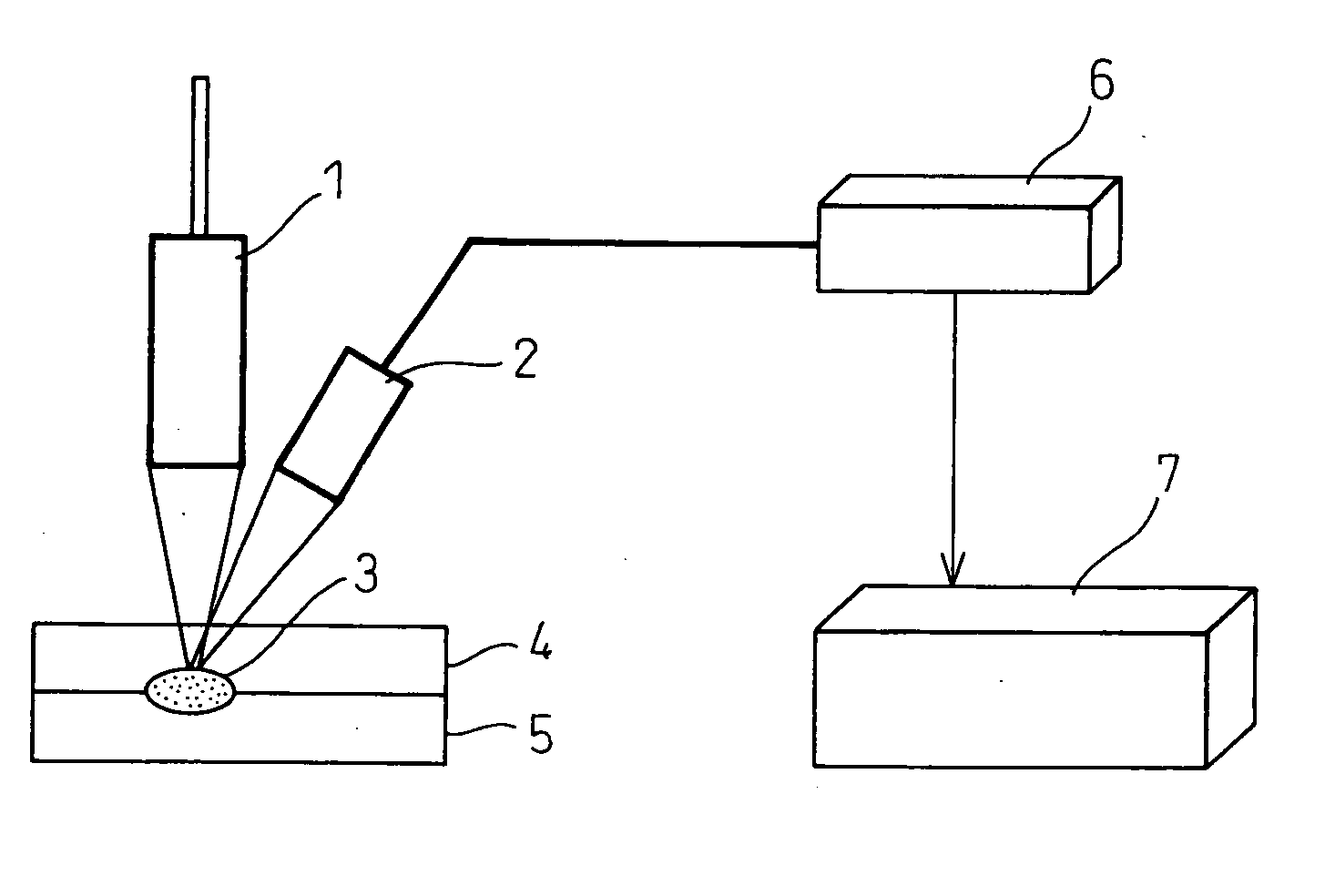
[0035] A laser deposition acceptance judgment method and its apparatus according to preferred embodiments of the invention will be hereinafter explained with reference to the accompanying drawings. FIG. 1 is a view for explaining a construction of the laser deposition acceptance judgment apparatus according to the invention. In the drawing, reference numeral 4 denotes a transmissible resin material having a high transmission factor to a laser beam. Reference numeral 5 denotes an absorptive resin material having a high absorption factor to the laser beam. These resin materials 4 and 5 are superposed with one another so that the transmissible resin material 4 is positioned on the laser irradiation side. The resin materials 4 and 5 superposed in this way are pressed and set by a support jig (not shown) and are held on a table (not shown). Generally, this table can move in both X- and Y-axes directions and can rotate on an X-Y plane.

[0036] Reference numeral 1 denotes a laser head for ir...

second embodiment

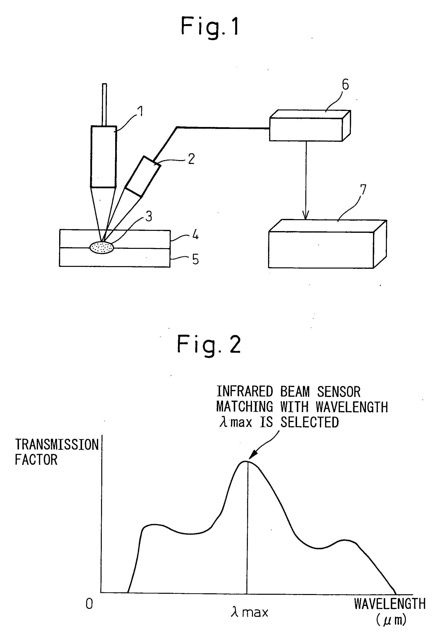
[0056] described above, the first infrared beam sensor 2A matching with the wavelength at which the transmission factor is low, and exothermy of the deposition portion 3 is not detected, is used to detect only the exothermic condition of the transmissible resin material 4. Next, the second infrared beam sensor 2B matching with the wavelength of the infrared beam having a high transmission factor is used to detect the exothermic condition of the deposition portion 3. In this way, it is possible to monitor whether or not the deposition portion 3 is formed by the application of suitable energy to the deposition portion 3 and whether or not the non-deposited portion is formed owing to the occurrence of the gap between both resin materials 4 and 5.

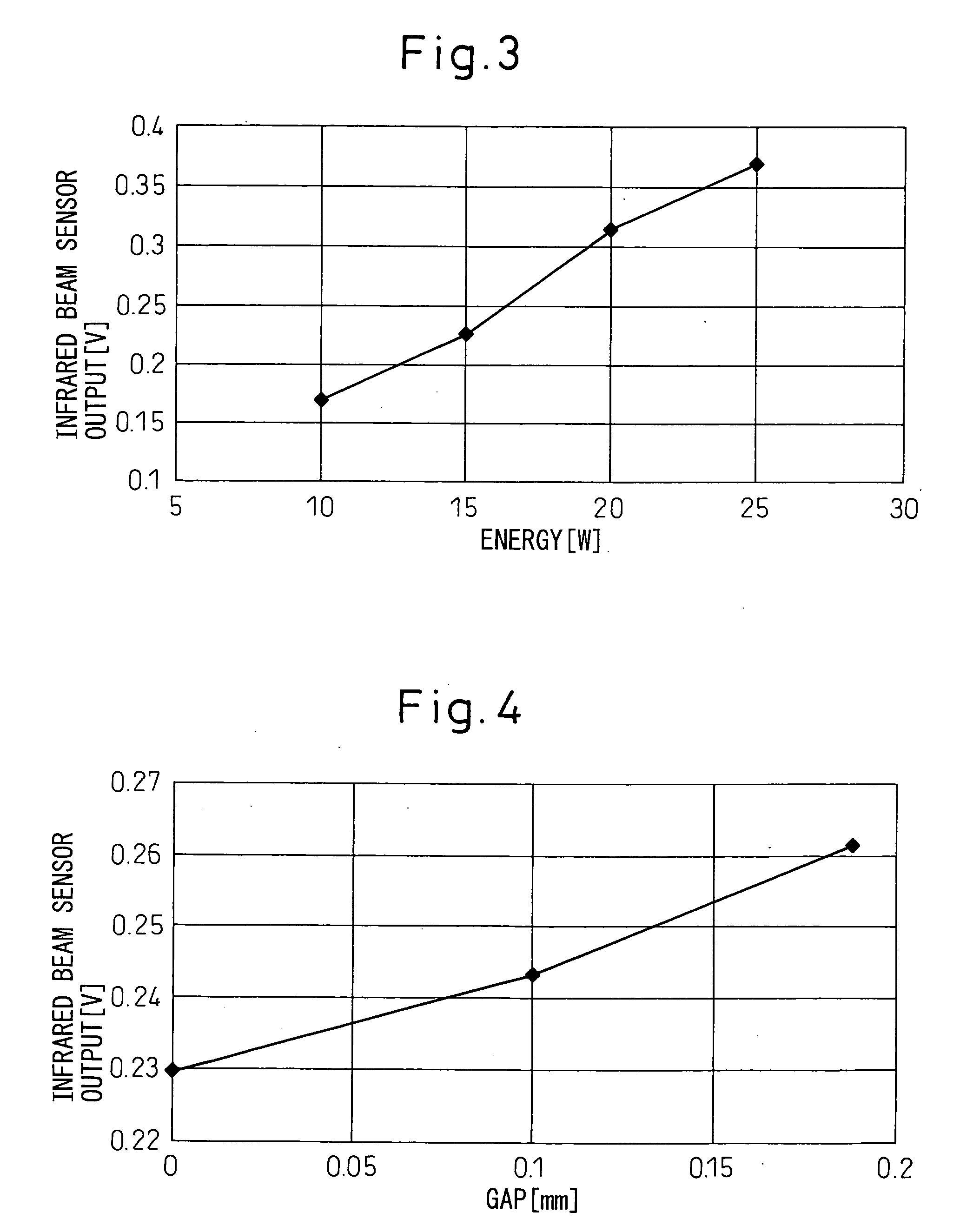
[0057] When the applied energy changes, exothermy of the transmissible resin material 4 changes as shown inFIG. 8. Therefore, the defect of the deposition portion 3 resulting from the energy change can be judged from the output result of the f...


PUM

PropertyMeasurementUnit
wavelengthaaaaaaaaaa
angleaaaaaaaaaa
widthaaaaaaaaaa

Abstract

Acceptance/rejection of a deposition condition is judged by detecting an exothermic quantity of a deposition portion 3 by using an infrared beam sensor 2 during laser deposition of a resin material 4 having transmissibility to a laser beam and a resin material 5 having absorptivity to the laser beam L. The exothermic condition of the deposition portion is detected by using an infrared beam sensor matching with a wavelength of an infrared beam having a high transmission factor from infrared beam transmission characteristics of the transmissible resin to judge whether or not suitable energy is applied to the deposition portion and whether or not the deposition portion is formed. The exothermic quantity of the transmissible resin is detected by an infrared beam sensor 2A to judge acceptance or rejection of the deposition portion even when the applied energy changes.

Description

BACKGROUND OF THE INVENTION [0001] 1. Field of the Invention [0002] This invention relates to a laser deposition (welding) acceptance judgment method for judging acceptance or rejection of a deposition (weld) portion welded by laser deposition (welding) and an apparatus for the method. [0003] 2. Description of the Related Art [0004] To reduce the weight and the cost, a resin molding has been used in recent years as a component of automobiles by, for example, forming the component from a resin. To improve productivity, such a resin molding is split molded in advance and the resulting split moldings are mutually welded to give a resin molding. [0005] To bond the resin materials to one another in this case, bonding by using an adhesive has been done but bonding is likely to fail due to influences of heat. Therefore, a method that heats and melts the resin materials by using a laser beam has been employed recently. [0006] Deposition (welding) of the resin materials by the laser beam is ...

Claims


Application Information

Patent Timeline
Patent Type & Authority Applications(United States)
IPC IPC(8): G03G15/32B23K26/00B29C65/16B29C65/82
CPCB29C65/1606B29C66/45B29C65/1654B29C66/1122B29C66/43B29C66/863B29C66/91216B29C66/91221B29C66/9592B29K2023/06B29K2023/12B29K2055/02B29K2059/00B29K2067/006B29K2069/00B29K2077/00B29K2081/04B29K2101/12B29C65/1635B29C66/961B29C66/9161B29C65/1687B29C65/1677B29C66/836B29C65/00B29C66/71B29C66/73921B29K2033/12
Inventor KAWAGOE, TADASHIKAWAMOTO, YASUNORI
Owner DENSO CORP
Why Eureka
Try Eureka