Rotational coupling device

a coupling device and rotating technology, applied in mechanical actuated clutches, brake discs, transportation and packaging, etc., can solve the problems of inefficient or isolated magnetic circuits within the devices, armature is difficult to disengage from the brake plate, and engagement surfaces of the devices still suffer from undesirable wear and tear, so as to achieve a more efficient magnetic circuit and facilitate the assembly of the conductor.

Active Publication Date: 2006-12-14
WARNER ELECTRIC TECH
View PDF46 Cites 27 Cited by
  • Summary
  • Abstract
  • Description
  • Claims
  • Application Information

AI Technical Summary

Benefits of technology

[0009] A rotational coupling device in accordance with the present invention represents an improvement over conventional devices because it creates a more effici

Problems solved by technology

The magnetic circuits within the device, however, are not optimally efficient or isolated from each other.
Further, the armature is difficult to disengage from the brake plate and the engagement surfaces of the dev

Method used


Image

  • Rotational coupling device
  • Rotational coupling device
  • Rotational coupling device

Examples


Embodiment Construction

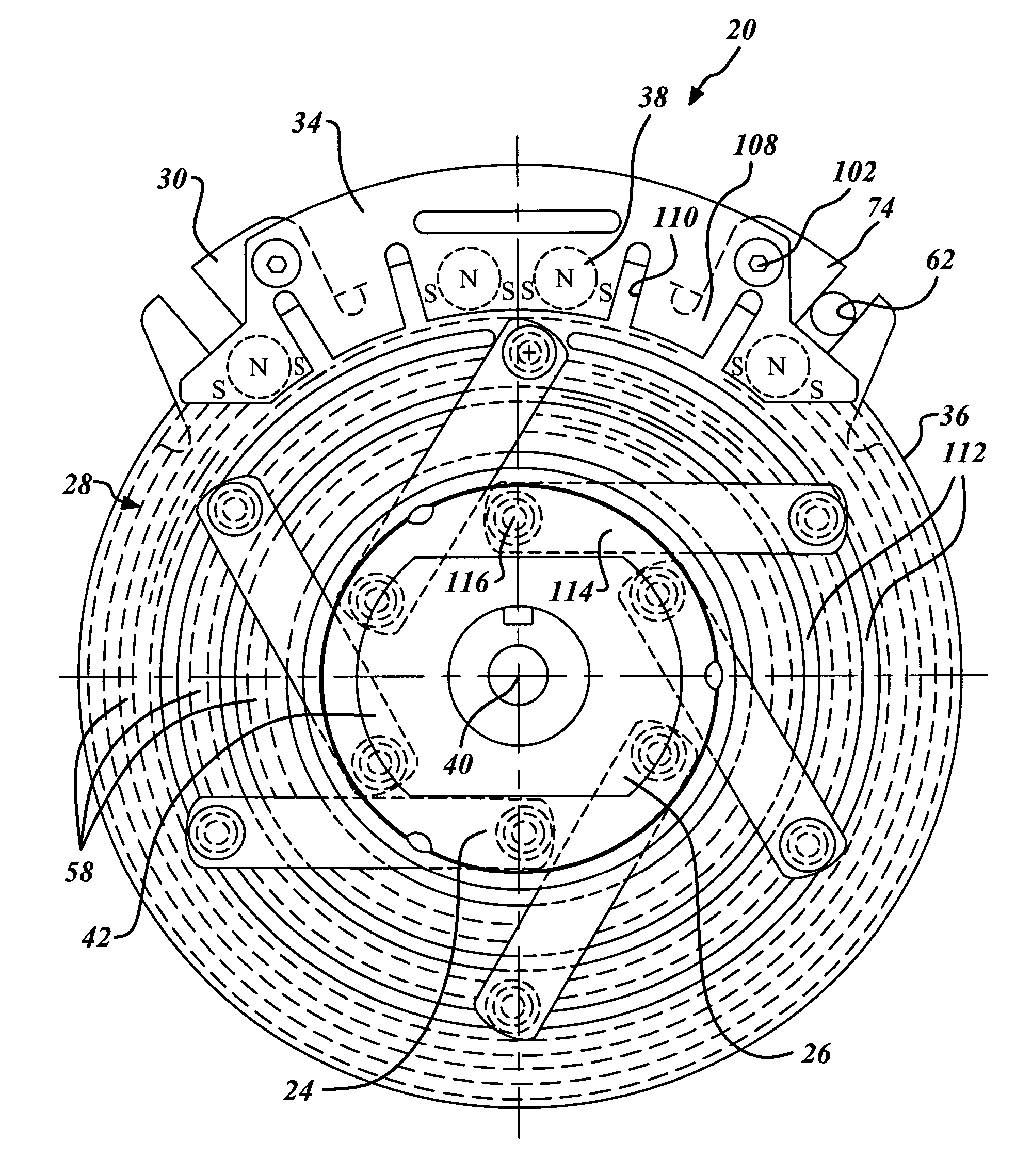
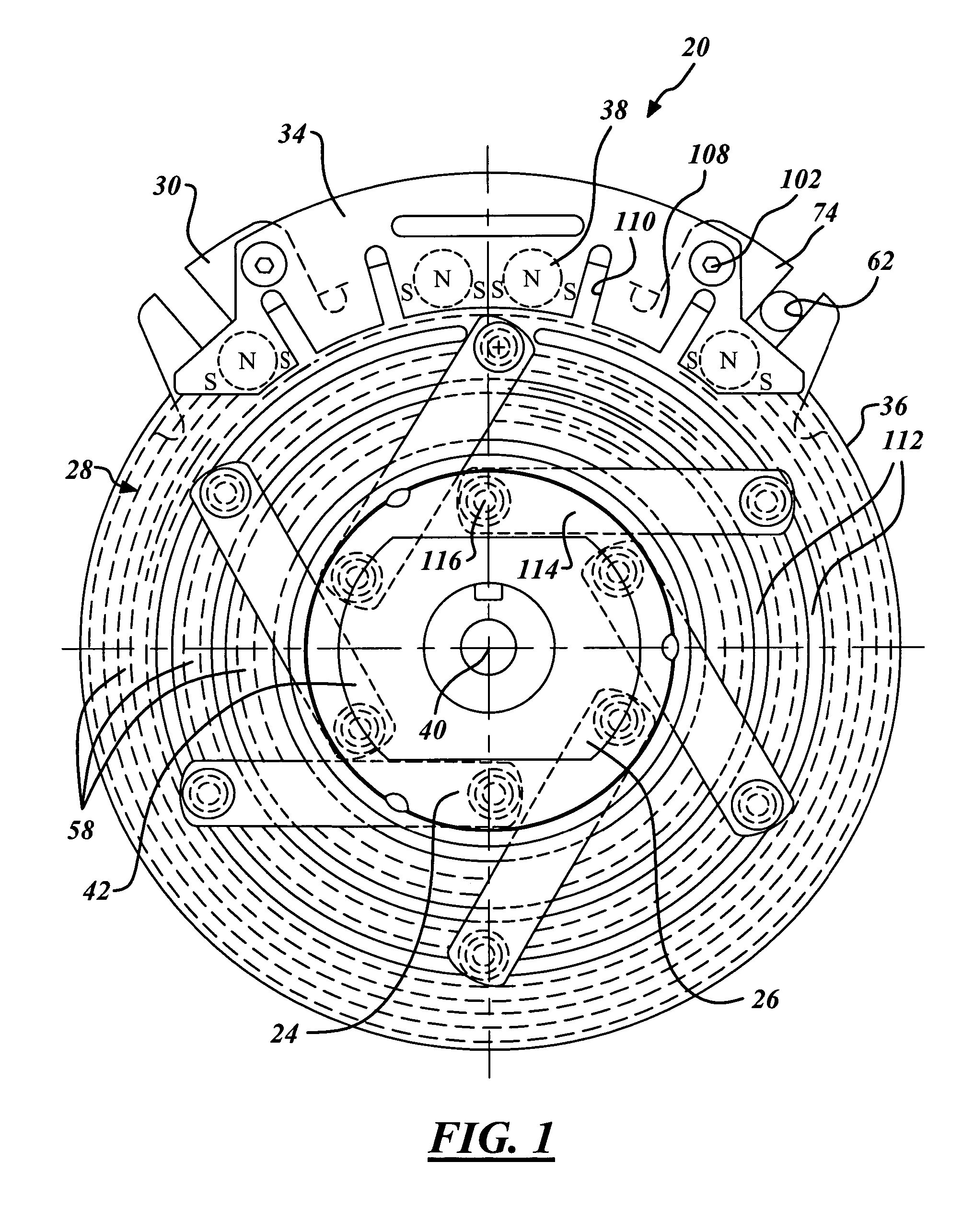
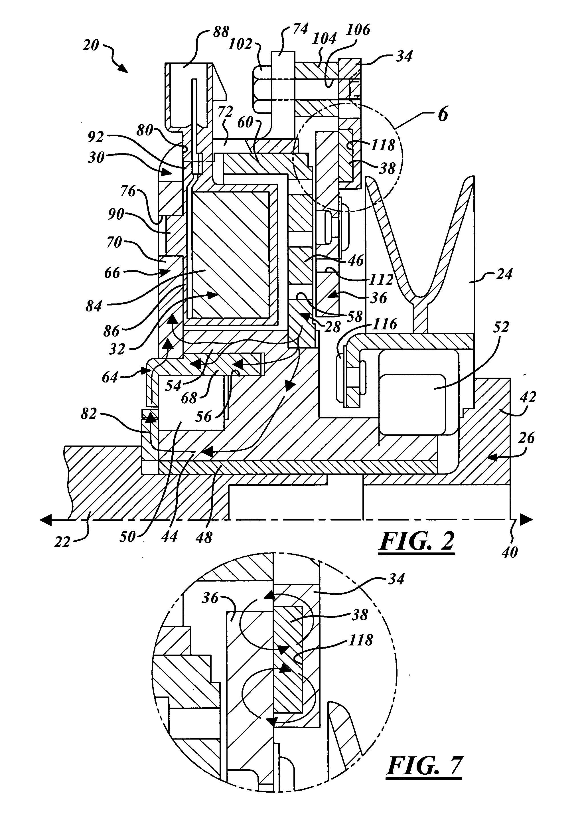
[0023] Referring now to the drawings wherein like reference numerals are used to identify identical components in the various views, FIGS. 1-2 illustrates a rotational coupling device 20 in accordance with one embodiment of the present invention. Device 20 functions as a clutch to selectively transfer torque from an input shaft 22 to an output member 24. Device 20 also functions as a brake on output member 24 when torque is not being transferred to output member 24. Device 20 may be provided for use in a riding lawnmower or similar device. It will be understood by those of ordinary skill in the art, however, that device 20 may be used in a wide variety of applications requiring a clutch or brake. Device 20 may include a spacer 26, a rotor 28, a field shell 30, an electrical conduction assembly 32, a brake plate 34, an armature 36 and one or more permanent magnets 38.

[0024] Input shaft 22 provides a source of torque for driving output member 24. Shaft 22 may be made from conventiona...


PUM


Abstract

A rotational coupling device for use as a clutch and/or brake is provided having improved magnetic efficiency and structural integrity. A field shell and a rotor of the device each define radially spaced, axially extending inner and outer poles. The inner pole of the rotor is disposed radially outwardly of the inner pole of the field shell resulting in improved magnetic efficiency.

Description

BACKGROUND OF THE INVENTION [0001] 1. Field of the Invention [0002] This invention relates to rotational coupling devices such as brakes and clutches and, in particular, to a rotational coupling device having improved magnetic efficiency and performance and improved structural characteristics. [0003] 2. Discussion of Related Art [0004] Rotational coupling devices such as clutches and brakes are used to control transfer of torque between rotational bodies. One type of conventional device is illustrated in U.S. Pat. Nos. 5,119,918, 5285,882 and 5,971,121, the entire disclosures of which are incorporated herein by reference. This device includes a rotor that is coupled to an input shaft for rotation with the input shaft about a rotational axis. A field shell is also disposed about the input shaft on one side of the rotor and is fixed against rotation. The field shell defines radially spaced, axially extending inner and outer poles between which an electrical conductor is disposed, faci...

Claims


Application Information

Patent Timeline
IPC IPC(8): F16D65/12
CPCF16D27/112F16D27/14F16D67/06F16D2129/065F16D2027/008F16D2121/20F16D2027/007F16D65/14
Inventor PARDEE, JAMES A.
Owner WARNER ELECTRIC TECH
Why Eureka
Try Eureka