
Two-shot or insert molded cuffs for welding onto clean air ducts

a technology of clean air ducts and molded cuffs, which is applied in the field of air ducts, can solve the problems of high cost burden, hampered approach, and material that cannot readily conform to sealing surfaces to make airtight seals, etc., and achieves the effect of enhancing the ultimate weld and being less expensiv

Inactive Publication Date: 2006-12-14
ADVANCED ELASTOMER SYST LP
View PDF3 Cites 40 Cited by
  • Summary
  • Abstract
  • Description
  • Claims
  • Application Information

AI Technical Summary

Benefits of technology

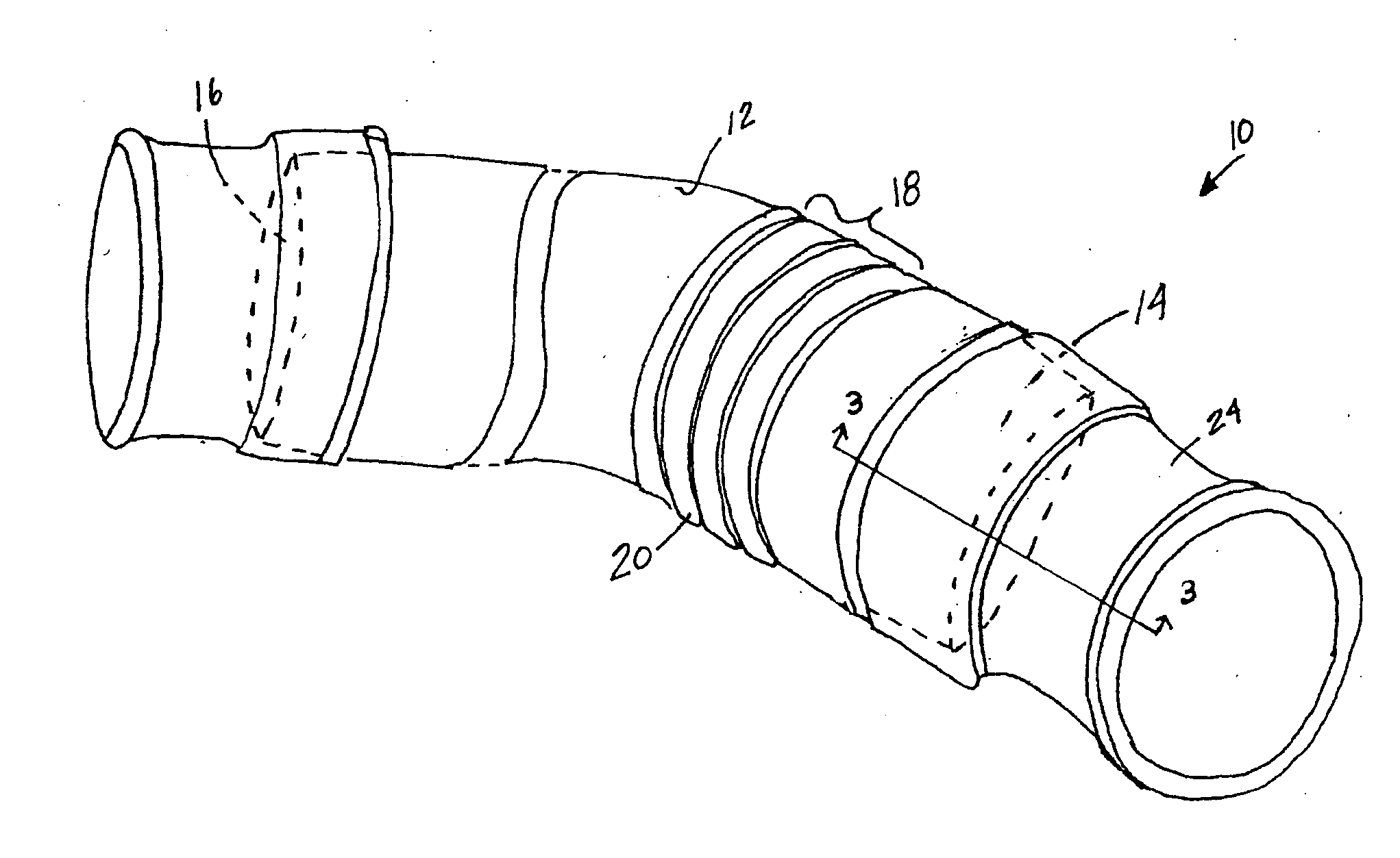
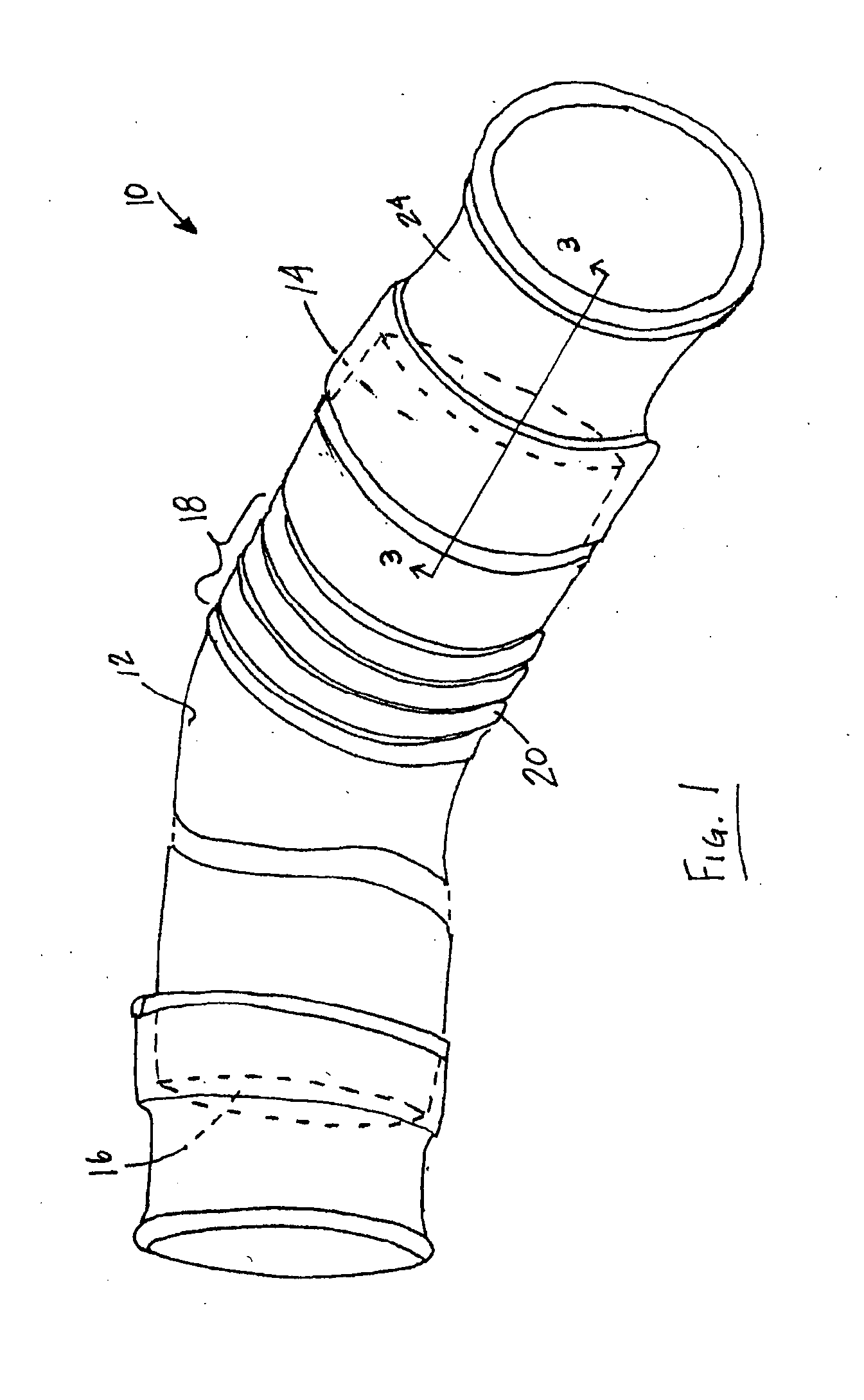
[0019] In one exemplary embodiment, a weldable layer section is added to the softer sealing component by a 2-shot injection molding process. 2-shot molding injection requires that the two materials to be bonded be chemically compatible, or no bonding occurs. In a 2-shot injection molding process, a single mold is utilized to form a unitary part comprising distinct “zones” comprising different materials. By this process, the more rigid polymer weldable section can be bonded to the softer elastomeric component to form the cuff member. In this exemplary process, a robust bond is formed at the interface between the weldable section and the cuff member because of precise part designs and higher pressure and temperature molding conditions. Ultimately, the weld between the cuff member and the air duct body is improved because of the chemical compatibility of the weldable section with both the elastomeric component of the cuff member and the air duct body. In one exemplary embodiment, the cuff member is adhered to the air duct body by a spin welding operation.
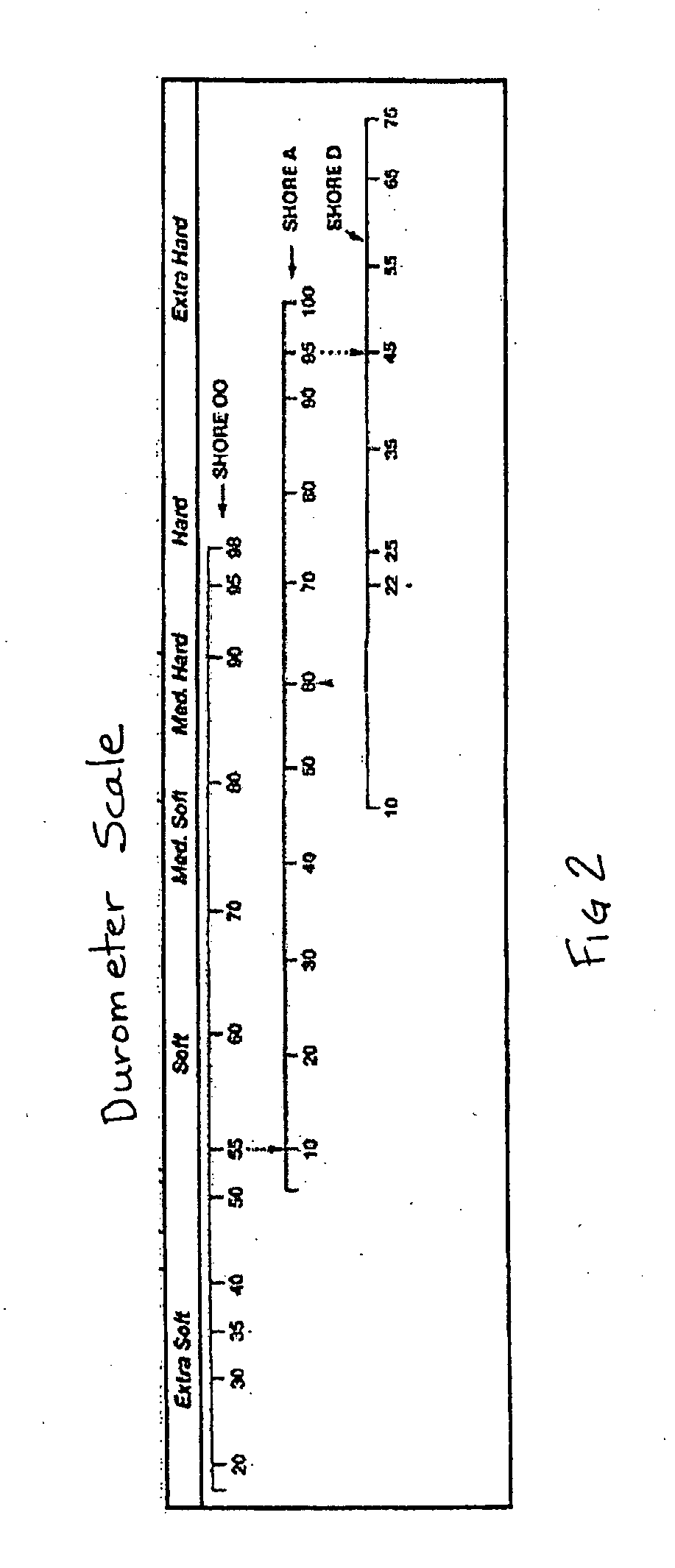
[0023] Both methods of forming the cuff member, i.e. 2-shot injection molding or insert injection molding, provide a weldable section to enhance the ultimate weld between a polyolefin (or rigid) thermoplastic air duct body and a cuff member comprising a softer sealing component. Thus, for example, a polypropylene air duct body could be welded to a cuff incorporating a softer (i.e., <80 durometer) sealing component via the polypropylene weldable section. The interface between the softer sealing component and the weldable insert is enhanced by the chemical compatibility of the materials. Likewise, the interface between the weldable insert and the body portion comprises an intimate joint between the materials used. Thus the weldable insert provides a means to join two materials having dissimilar physical properties (i.e., soft vs. rigid).
[0024] One advantage of the exemplary embodiments is that a cuff member comprising a softer elastomeric material may be welded to an air duct body.
[0025] Another advantage of the exemplary embodiments is that the insert is used to bridge the gap in chemical compatibility between the softer cuff member and the more rigid air duct body.
[0026] Another advantage of the exemplary embodiments is that the less expensive materials used to form the air duct body can be robustly welded to sealable cuff members.
[0027] Another advantage of exemplary embodiments is that an air duct body and a cuff member comprising a softer elastomeric component may be spin welded together.

Problems solved by technology

Although materials such as polypropylene are adequate for air duct bodies, the material does not readily conform to sealing surfaces to make airtight seals.
However, this approach carries a high cost burden.
Additionally, this approach is hampered by the durometer limits of material that can be employed.
Also, the air duct geometry may also limit its ability to be produced with good sealing and assembly characteristics.
However, process and material limitations prevent the production of an air duct with cuff material exhibiting less than about 80 A durometer.
Disadvantages associated with the over-molding process include high tooling cost as both a blow mold and an injection mold must be used to produce a finished part.
Injection tooling can be complex.
Also, there may be an increase in cycle times due to the manual loading of the blow molded part into the injection mold.
In practice, the strength of the bond between dissimilar materials is limited by the pressure and temperature associated with the welding process.
In addition, this approach is limited by the inability to generate a robust weld with elastomers having durometer values below 80 A due to the low polymer content present in the softer elastomers.

Method used


Image

  • Two-shot or insert molded cuffs for welding onto clean air ducts
  • Two-shot or insert molded cuffs for welding onto clean air ducts
  • Two-shot or insert molded cuffs for welding onto clean air ducts

Examples


Embodiment Construction

Definitions:

[0034] Thermoplastic Elastomer (TPE): a diverse family of rubber-like materials that, unlike conventional vulcanized rubbers, can be processed and recycled like thermoplastic materials. Typical examples include blends of “hard” crystalline, semi-crystalline, or glassy polymers (for instance those having a Tm greater than about 110° C. or Tg greater than about 60° C., as measured by differential scanning calorimetry (DSC), more preferably with amorphous or low-crystallinity polymers (Tm less than about 90° C. or Tg less than 60° C. by DSC). Examples of hard polymers include the non-polar and polar engineering resins such as polypropylene, polyethylene, polyamide, polycarbonate, and polyester resins. The “soft” polymers include most rubbers, particularly the non-polar olefin rubbers, for hard polyolefins, and polar rubbers for polar hard resins. Non-polar rubbers include ethylene-propylene rubber, very low density polyethylene copolymers comprising C4 to C8 α-olefin or v...


PUM

PropertyMeasurementUnit
Tgaaaaaaaaaa
Tgaaaaaaaaaa
Tmaaaaaaaaaa

Abstract

An air duct includes a rigid thermoplastic body having softer elastomeric cuff members welded to the ends thereof. The cuff members comprise an outer sealing component and a weldable insert bonded to at least a portion of the inner surface. The cuff members are adhered to the thermoplastic body at the weldable insert through a spin welding or other suitable welding process. The chemical compatibility between the insert and the thermoplastic body provides a robust weld at the interface.

Description

FIELD OF INVENTION [0001] The present invention relates broadly to the field of air ducts, and more particularly to a coupling member and a method of joining an elastomeric cuff comprising a first material to the open end of a molded air duct body formed of a second material. The air ducts may be particularly adapted for vehicular use. BACKGROUND ART [0002] Air ducts are known for use on internal combustion engine applications for a number of purposes. For example, they are used to transport clean air from an air filter through the air intake system. They are also used to transport air from the engine compartment to and within the passenger compartment. [0003] It is desirable to have an air duct with good sealing qualities at the interface between the body of the air duct and the vehicular or other components. Although materials such as polypropylene are adequate for air duct bodies, the material does not readily conform to sealing surfaces to make airtight seals. [0004] Some prior ...

Claims


Application Information

Patent Timeline
Patent Type & Authority Applications(United States)
IPC IPC(8): F16L25/00B29C65/00
CPCB29C45/14598B29C66/12841B29C65/0672B29C65/5057B29C65/7802B29C66/5221B29L2031/24B29L2031/265F16L47/02F24F13/0209B29C66/5223F02M35/10321F02M35/10347F02M35/1036F02M35/10144B29C66/52292B29C65/4815B29C66/1282B29C45/16B29C66/71B29K2023/22B29K2023/16B29K2023/12B29K2023/06B29K2021/003B29K2007/00
Inventor COLLINS, DANIEL J.
Owner ADVANCED ELASTOMER SYST LP
Learn More