The latter rings, although being non-rigid or flexible, are however generally not elastic and are as such not expandable as a function of the varying
cardiac cycle parameters and associated ventricular
mechanics.
This is largely due to the technically demanding nature of current valve repair or sparing procedures such as the most common “David Reimplantation” or “Yacoub Remodelling”.
Due to this lack of specially designed
prosthesis and apparatus, practicing surgeons must often resort to “off-
label use” of existing
implant materials to tailor a surgical solution during the surgical intervention.
One of the main drawbacks of the Bentall procedure is that the patient is placed on long-term anticoagulation therapy in Bentall procedures using mechanical valves, and a risk of valve degradation and need for re-operation in Bentall procedures using a
bioprosthetic valve.
The procedure is generally long and difficult to perform, and often results in leaflet
impact or
concussion with the walls of the Dacron
prosthesis during the ejection phase of the
cardiac cycle.
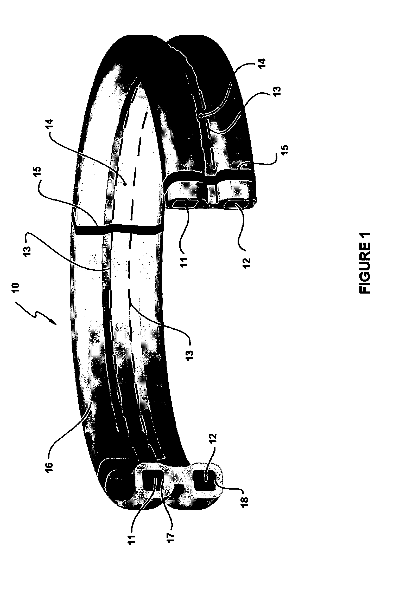
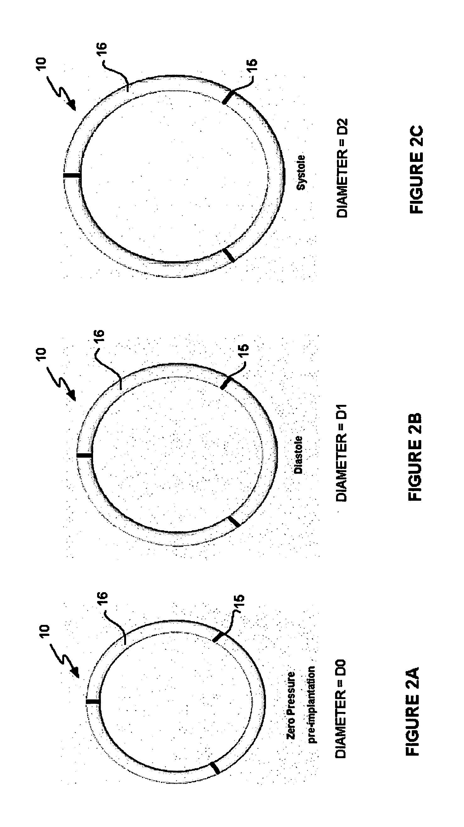
In addition, the absence of radial compliance of the Dacron root
prosthesis does not allow for an increase in
diameter at the sinotubular junction STJ during ejection, which is an important aspect in providing optimal blood transport while preserving valve dynamics and
valve leaflet durability.
As such, the normal valve
physiology is compromised in this valve-sparing intervention.
Although this method addresses some of the problems of the reimplantation method, it does not directly constrain the valve annulus diameter, which has been seen to result in annular dilatation over time.
As such, this procedure is not well suited for resizing a dilated valve annulus, and may be limited to replacing aneurysmal aortic tissue.
Nonetheless, in the remodelling valve-sparing intervention, the normal
native valve physiology is compromised, and the effectiveness of resizing a dilated aortic annulus, or preventing its future dilatation, with a scalloped vascular conduit remains questionable.
Although useful and widely accepted for some aortic reconstruction procedures, conventional valve-sparing procedures and devices nevertheless suffer from numerous drawbacks or shortcomings that are manifested and become apparent both during the operative and post-operative periods.
Typical prior art devices and methods for aortic reconstruction or valve sparing interventions do not offer a dynamic device configuration that may advantageously vary during the different phases of the
cardiac cycle, and consequently restore or preserve normal aortic valve
physiology.
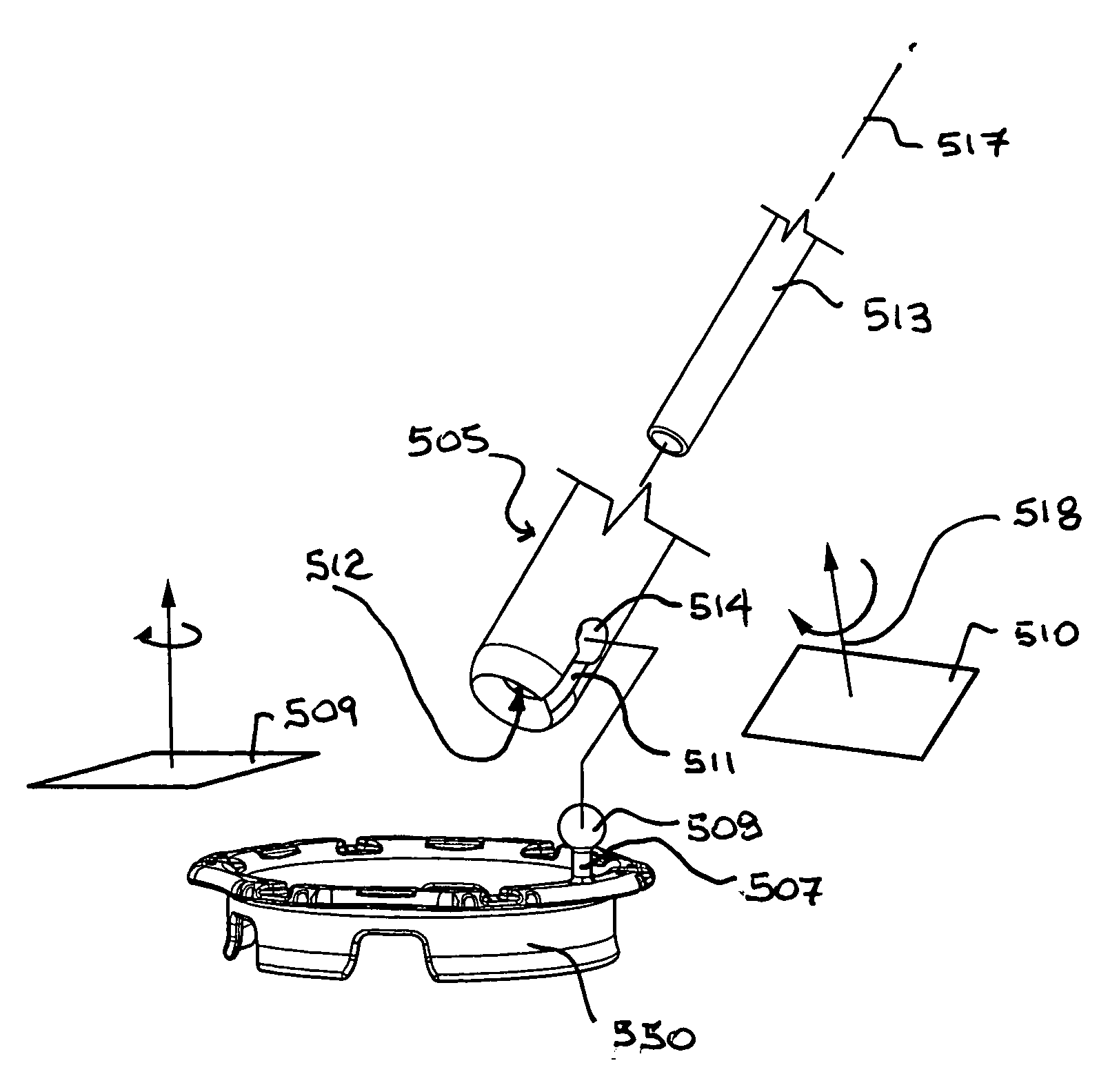
Such a mechanical limitation does not allow the surgeon to orient the holder body relative to the
handle in order to optimize the delivery of the prosthesis to the
implant site.
However, such malleable handles are generally difficult to reshape in different bent configurations once they have been initially bent.
Moreover, the material of such malleable handles work hardens with repeat bending making it progressively more difficult to easily bend such handles.
Some of the drawbacks associated with Nitinol handles include cost, and generally insufficient stiffness of such handles given the highly elastic properties of Nitinol.
Such threaded interfaces do not provide the ability to orient the holder body relative to the
handle.
As well, such threaded interfaces generally do not provide ability for rapid
changeover of prosthesis holders or sizers, since unthreading and rethreading is a relatively lengthy process with inherent risks of cross-threading.
Current alternatives to threaded interfaces, such as quarter turn bayonet arrangements, are also currently used but also do not offer the ability to orient the holder body relative to the handle.
Such bayonet arrangements are relatively large in size thereby creating greater obstruction to the surgeon view of the
surgical site.
Such obstruction is particularly problematic when the surgeon is visually assessing the suitability of a selected size of prosthesis.
Also, bayonet arrangements are generally more difficult to clean and sterilize given the design of cooperating bayonet features such as blind holes and elongated slots and dogs.
This technique does not provide a positive lock between the handle and holder (or sizer) and the engagement forces may vary due to dimensional tolerances and wear at such interfaces.
Moreover, it may be difficult to remove the holder from the handle when the holder is placed adjacent to the
native valve during the surgical intervention, due to the variability in frictional engagement and since the separating force must be applied to the holder in the
chest cavity while the handle is pulled away from the holder away from the
chest cavity.
Alternatively, the friction fit may be too loose resulting in holder (or sizer) easily disengaging from the handle making for an unsecure assembly.

