Vibration stress relief of superalloy components

a superalloy and stress relief technology, applied in the direction of turbines, soldering devices, manufacturing tools, etc., can solve the problem of producing enough vibration to risk damaging the substra

Inactive Publication Date: 2006-12-21
SIEMENS ENERGY INC
View PDF3 Cites 16 Cited by
  • Summary
  • Abstract
  • Description
  • Claims
  • Application Information

AI Technical Summary

Benefits of technology

[0009] The present invention provides a method of stress relief for superalloy components such as the blades used within

Problems solved by technology

Such a frequency will produce sufficient vibration to effectively reduce stresses in

Method used


Image

  • Vibration stress relief of superalloy components
  • Vibration stress relief of superalloy components
  • Vibration stress relief of superalloy components

Examples


Embodiment Construction

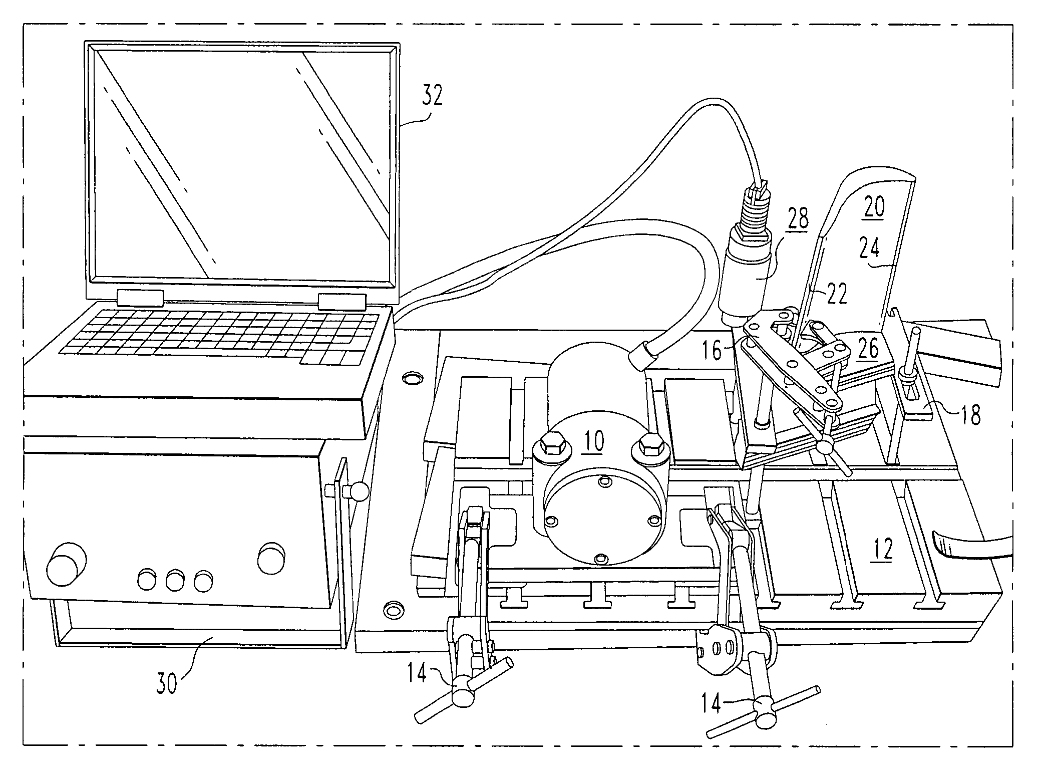
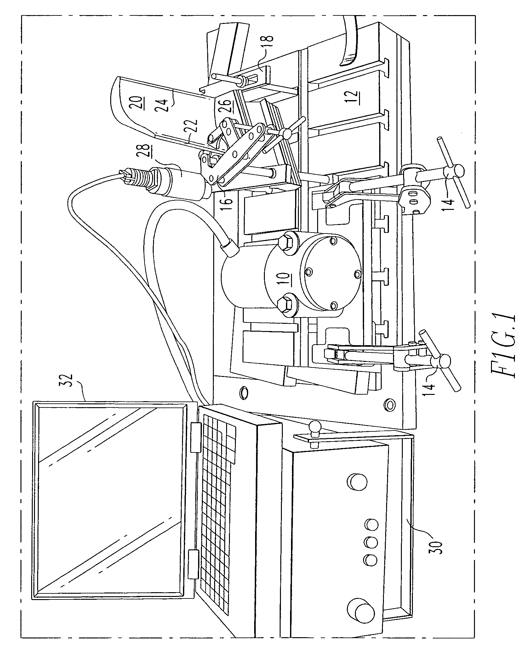
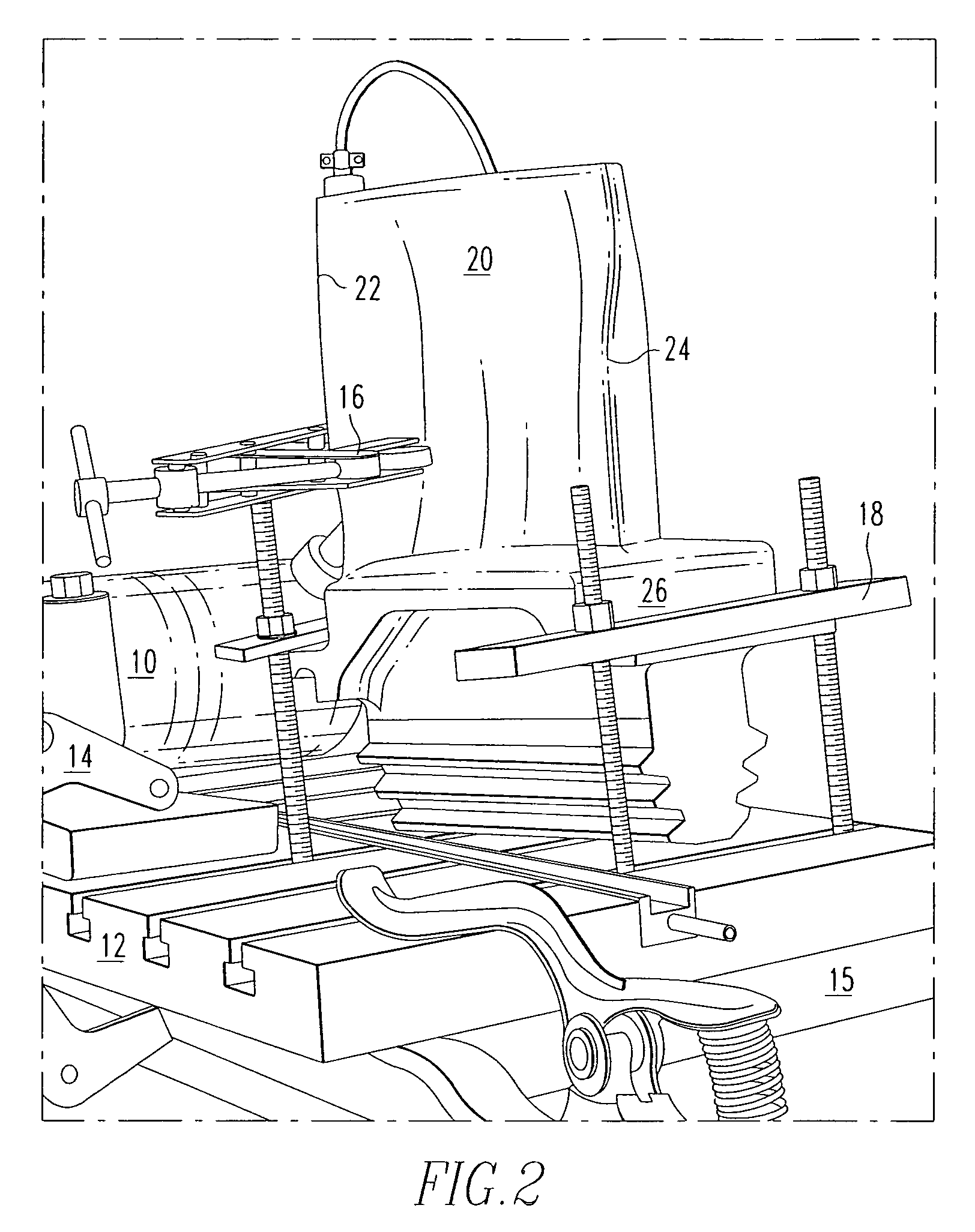
[0019] The present invention provides a method of stress relief for superalloy components, for example, the blades of a combustion turbine.

[0020] An apparatus for performing vibration stress relief is illustrated in FIGS. 1-3. The apparatus includes a preferred force inducer 10 for the illustrated example using a blade weighing about 12-20 lbs. should be capable of applying up to 190 lbs. of force. One example of a preferred force inducer is a Meta-Lax Model V8 force inducer. Meta-Lax equipment is available from Bonal Technologies, Inc., located in Royal Oak, Mich. The force inducer 10 is clamped to a bedplate 12 by the clamps 14. Although not shown on the drawing, it is well understood by those skilled in the art of welding that the force inducer 10 must be electrically insulated from the bedplate 12 by appropriate insulating materials therebetween. Additionally, the bedplate 12 is atop an elastomeric, electrically insulating pad 15, for example, a rubber pad that may have a thick...


PUM

PropertyMeasurementUnit
Frequencyaaaaaaaaaa
Frequencyaaaaaaaaaa
Weightaaaaaaaaaa

Abstract

A method of conditioning and stress relief for superalloy components includes vibrating the component during welding at a subharmonic frequency. The proper frequency is selected to be below a harmonic frequency, and to produce an amplitude in the range of ⅓ to ½ the amplitude produced by a harmonic frequency. The component to be repaired is vibrated during and after welding at this frequency.

Description

BACKGROUND OF THE INVENTION [0001] 1. Field of the Invention [0002] The present invention relates to stress reduction during welding. More specifically, the invention provides a method of weld conditioning and stress relief wherein the component being welded is vibrated during welding to reduce stresses in the component. [0003] 2. Description of the Related Art [0004] Welding is typically used to perform repairs on components of various equipment that is subject to harsh environments. One example is the repair of blades for combustion turbines by gas tungsten arc welding (GTAW) or plasma arc welding (PAW) welding. Such blades are subject to high temperature and high stresses during operation of the turbine. [0005] Combustion turbine blades are typically made from superalloys, which are defined herein as nickel based alloys containing aluminum and / or titanium as precipitation hardening elements, or cobalt based alloys. These components are often made by casting, after which they are ...

Claims


Application Information

Patent Timeline
IPC IPC(8): B23K31/02
CPCB23K9/022B23P6/002B23K2203/08B23K2201/001B23K2101/001B23K2103/26
Inventor CHITTY, JOHN
Owner SIEMENS ENERGY INC
Why Eureka
Try Eureka