Apparatus and method for coupling microfluidic systems with electrospray ionization mass spectrometry utilizing a hydrodynamic flow restrictor

a microfluidic system and electrospray ionization technology, applied in chemical methods analysis, material testing goods, particle separator tubes, etc., can solve the problems of hdr not providing adequate resistance to flow, difficult to fill the channel, and complicating the flow through the electrophoretic channel of the devi

Inactive Publication Date: 2006-12-21
WEST VIRGINIA UNIV RES
View PDF2 Cites 26 Cited by
  • Summary
  • Abstract
  • Description
  • Claims
  • Application Information

AI Technical Summary

Benefits of technology

[0011] In an embodiment, a method is disclosed for utilizing a hydrodynamic flow in conjunction with an electroosmotic flow in order to deliver a sample to a mass spectrometer. In an embodiment, the method comprises providing a substrate having an input channel and an output channel, wherein a main channel engages the input channel to the output channel. In an embodiment, the method comprises delivering a sample to the input channel wherein a low electoosmotic force drives the sample through the

Problems solved by technology

However, the polymer monolith results in too large a backpressure in the separation channel, which makes it difficult to fill the channels.
Moreover, the glass surface of the microchannel and the polymer monolith region exhibit different electroosmotic flow properties which complicates the flow through the electrophoretic channels of the device.
In addition, because of the

Method used


Image

  • Apparatus and method for coupling microfluidic systems with electrospray ionization mass spectrometry utilizing a hydrodynamic flow restrictor
  • Apparatus and method for coupling microfluidic systems with electrospray ionization mass spectrometry utilizing a hydrodynamic flow restrictor
  • Apparatus and method for coupling microfluidic systems with electrospray ionization mass spectrometry utilizing a hydrodynamic flow restrictor

Examples


Embodiment Construction

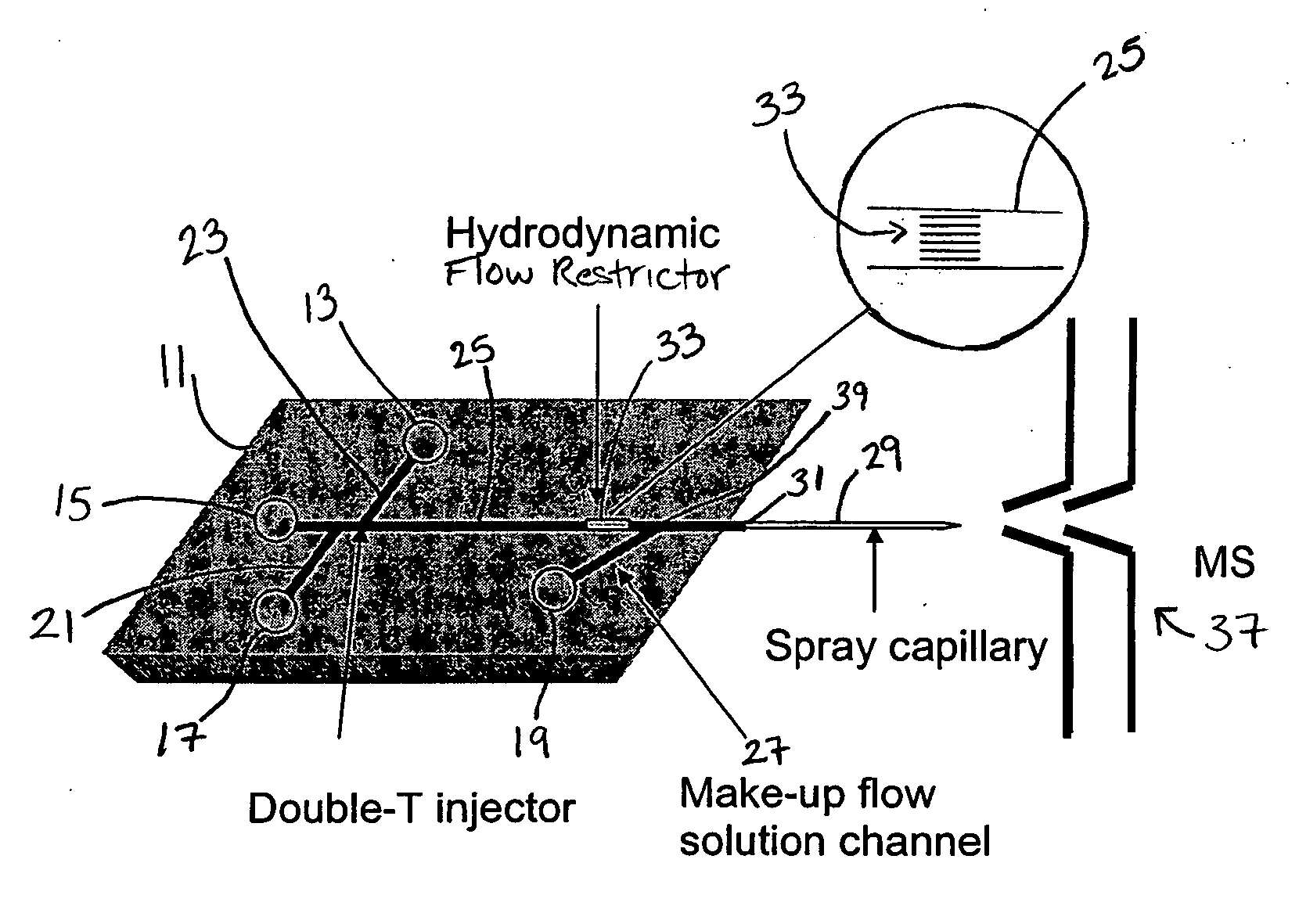
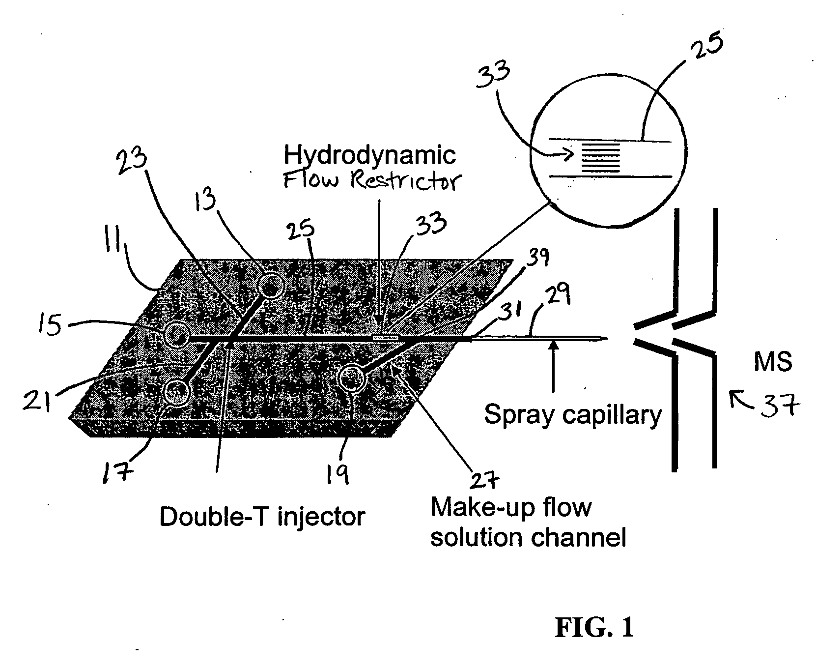
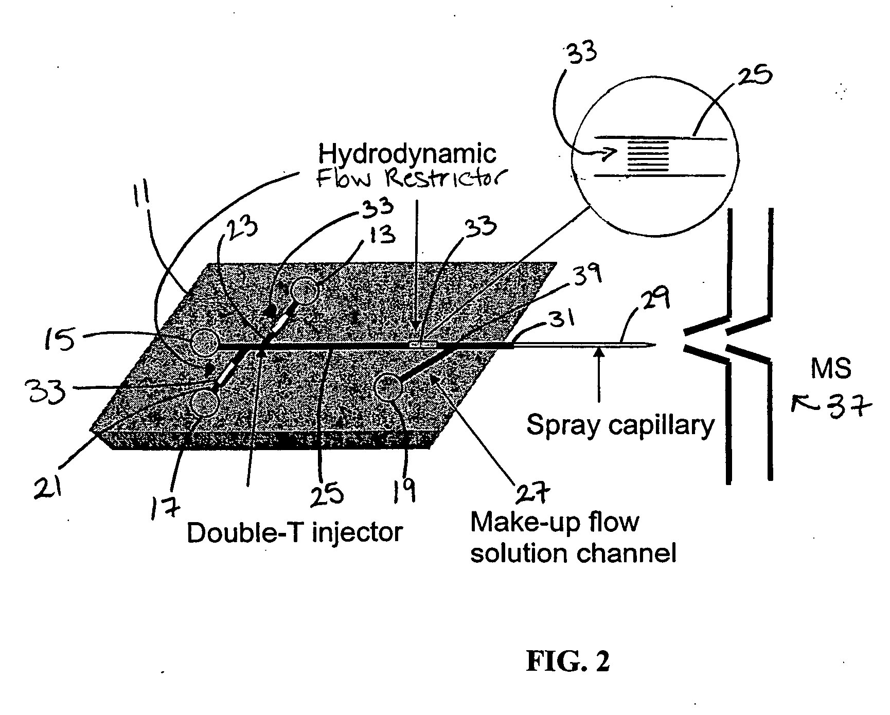
[0024] In an embodiment, the microchip-ESI-MS interface integrates the introduction of a sheath solution and application of the electrospray voltage onto the microfluidic device. In an embodiment, the interface design substantially prevents back-flow of solution into the separation channel and allows use of an electrophoretic system with low EOF. The use of low EOF systems is particularly important for proteins, because coatings that minimize protein absorption also minimize EOF. In an embodiment, the apparatus and method can decouple the ESI and capillary electrophoresis (“CE”) voltages to enable upstream fluidic control for sample handling while samples are infused into the mass spectrometer.

[0025]FIG. 1 shows an embodiment wherein a microfluidic device 11 is engaged to a mass spectrometer 37. The microfluidic device 11 comprises a main channel 25 wherein the main channel engages an input channel 21 and a waste channel 23. In an embodiment, a high voltage electrode 15 is position...


PUM


Abstract

A microfluidic device is disclosed wherein a hydrodynamic flow restrictor is positioned in a main channel; a make-up flow channel engages the main channel at a position between the hydrodynamic flow restrictor and an output channel. The hydrodynamic flow restrictor substantially negates a hydrodynamic backpressure in the main channel to the extent that low electroosmotic flow may be utilized in the main channel. Further, a method is disclosed wherein a sample is delivered to the main channel and low EOF drives the sample through the main channel. The method comprises positioning a hydrodynamic flow restrictor in the main channel and delivering a make-up solution via hydrodynamic flow to the main channel at a position between a hydrodynamic flow restrictor and the output channel. The hydrodynamic flow restrictor substantially negates a hydrodynamic backpressure in the main channel to the extent that low electroosmotic flow may be utilized in the main channel.

Description

GOVERNMENT SUPPORT [0001] The invention was supported, in whole or in part, by Grant No. RR16440 from the National Institute of Health. The Government has certain rights in the invention.RELATED APPLICATIONS [0002] None. FIELD OF THE INVENTION [0003] The invention relates to microfluidic devices. More specifically, the invention discloses an apparatus and method for coupling microfluidic systems with electrospray ionization mass spectrometry utilizing a combination of hydrodynamic flow and electroosmotic flow. BACKGROUND OF THE INVENTION [0004] Microfluidic analytical systems have been engineered for sample preparation, solid phase extraction, tryptic digestions and separations of biological samples. Massive parallelism, shorter analysis time, increased separation efficiencies, higher sensitivities and reduced waste generation can be achieved with these devices. Microfluidic devices are characterized by their zero dead volume intersections and small channels, having depths and width...

Claims


Application Information

Patent Timeline
IPC IPC(8): B01L3/00
CPCB01L3/0268B01L3/502746B01L2300/0816H01J49/165B01L2400/0487B01L2400/086H01J49/0018B01L2400/0418
Inventor TIMPERMAN, AARON T.
Owner WEST VIRGINIA UNIV RES
Why Eureka
Try Eureka