Hyperthermia treatment and probe therefor

a technology of hyperthermia and probes, applied in the field of hyperthermia treatment and probes therefor, can solve the problems of difficulty for surgeons to achieve controlled heating, no system available, disclosure of patents, etc., and achieve commercially viable hyperthermic treatment systems

Inactive Publication Date: 2006-12-21
MONTERIS MEDICAL
View PDF38 Cites 43 Cited by
  • Summary
  • Abstract
  • Description
  • Claims
  • Application Information

AI Technical Summary

Benefits of technology

[0016] It is one object of the present invention, therefore, to provide an i...

Problems solved by technology

It is difficult therefore for the surgeon to effect a controlled heating which heats all of the lesion while minimizing damage to surrounding tissue.
The imaging system thus generates for the surgeon a location of the lesion to be excised but there is no system available which allows the surgeon to use the imaging system to control the heating effect.
The disclosure of the patent has not led to a commercially viable hyperthermic treatment system.
Again this patented arrangement has not led to a commercially viable hypertherm...

Method used


Image

  • Hyperthermia treatment and probe therefor
  • Hyperthermia treatment and probe therefor
  • Hyperthermia treatment and probe therefor

Examples


Embodiment Construction

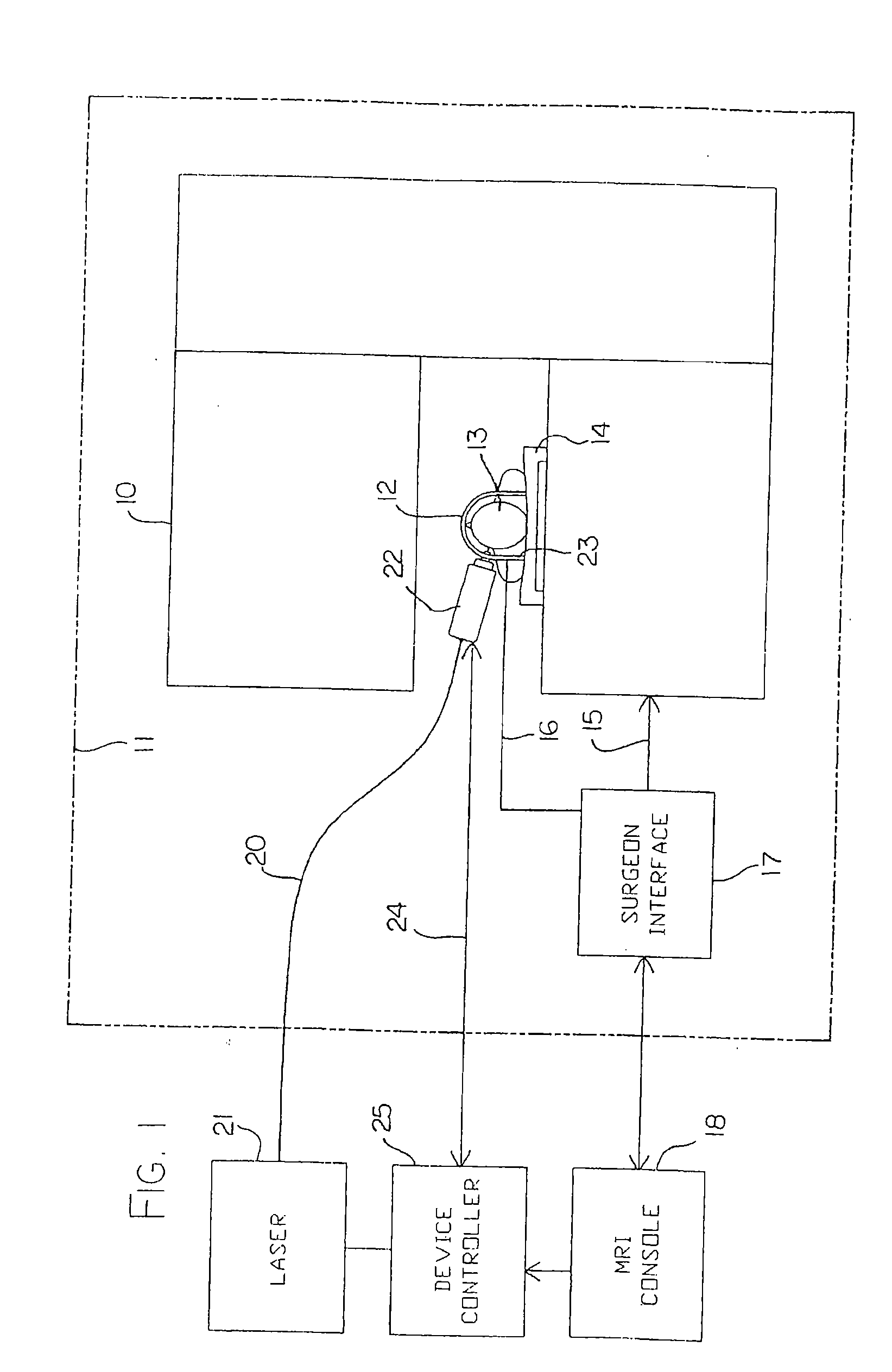
[0075] In FIG. 1 is shown schematically an apparatus for carrying out MRI controlled laser treatment. The apparatus comprises a magnetic resonance imaging system including a magnet 10 provided within a shielded room 11. The magnet 10 can be of any suitable construction and many different magnet arrangements are available from different manufacturers. The magnet includes field coils for generating variations in the magnetic field which are not shown since these are well known to one skilled in the art together with a radio frequency antenna coil which receives signals from the sample in this case indicated as a human patient 13.

[0076] The patient 13 rests upon a patient support table 14 on which the patient is supported and constrained against movement for the operative procedure. The fields of the magnet are controlled on an input control line 15 and the output from the antenna coil is provided on an output line 16 both of which communicate through a surgeon interface 17 to the con...


PUM


Abstract

An MRI guided surgical apparatus includes a heat source formed by a laser and an optical fiber carrying the heat energy into a part to be coagulated by hyperthermia with an end reflector to direct the energy in a beam to one side of the fiber end. A reinforcing sleeve for the fiber is mounted in a shielded, Piezo-electric motor which causes movement of the fiber longitudinally and angularly within a rigid elongate cannula. A magnetic resonance imaging system is arranged to generate a series of output signals over a period of time representative of temperature in the part as the temperature of the part changes during that time. The heat source is controlled in heat energy applied and location and orientation of the beam to stop heating when the temperature at the boundary of a tumor reaches the required hyperthermic temperature. Cooling of the tip portion of the probe is effected by expansion of a supplied cooling fluid in gaseous form through a restrictive orifice into an expansion zone at the probe end. The fiber is thus encased in a stiff tubular titanium probe with a relatively small fluid supply duct along the inside of the probe with the interior of the probe acting as a return duct for the expanded gas. Thus the fiber end is contained in gas rather than liquid and the temperature of the probe end can be monitored by a sensor in the probe end and controlled by controlling the pressure in the supplied cooling fluid. The probe is driven in the longitudinal and rotational directions to move the fiber tip.

Description

CROSS REFERENCE TO RELATED APPLICATIONS [0001] This application is a continuation of U.S. application Ser. No. 10 / 014,846, filed Dec. 14, 2001, which is a continuation-in-part of PCT Application No. CA01 / 00905 filed Jun. 15, 2001, which claims priority to U.S. application Ser. No. 09 / 593,699, filed Jun. 15, 2000, now issued as U.S. Pat. No. 6,418,337, the entireties of which are hereby incorporated by reference. [0002] This invention relates to a method and apparatus for hyperthermia treatment in a patient.BACKGROUND OF THE INVENTION [0003] The treatment of tumours by hyperthermia is known. Thus tumours and other lesions to be treated can in one known process be heated above a predetermined temperature of the order of 55° C. so as to coagulate the portion of tissue heated. The temperature range is preferably of the order of 55 to 65° C. and does not reach temperatures which can cause carbonization or ablation of the tissue. [0004] One technique for effecting the heating is to insert...

Claims


Application Information

Patent Timeline
IPC IPC(8): A61B18/18A61B18/20A61B17/00A61B18/00A61B18/22A61B18/24A61B19/00A61F7/00A61N5/06
CPCA61B18/1815A61B18/22A61B18/24A61B2019/5236A61B2018/00023A61B2018/2272A61B2017/00084A61B2090/374
Inventor TORCHIA, MARK G.TYC, RICHARDPACAK, JOHN S.
Owner MONTERIS MEDICAL
Why Eureka
Try Eureka