Planar robot with parallel axes and fixed motors for a water jet cutter

Active Publication Date: 2006-12-28
G E LEBLANC
View PDF8 Cites 21 Cited by
  • Summary
  • Abstract
  • Description
  • Claims
  • Application Information

AI Technical Summary

Benefits of technology

[0006] The object of the present invention is to provide a planar robot for use to cut products, which comprises a c

Problems solved by technology

Prior art systems are interesting but often have high inertias in the mechanisms req

Method used


Image

  • Planar robot with parallel axes and fixed motors for a water jet cutter
  • Planar robot with parallel axes and fixed motors for a water jet cutter
  • Planar robot with parallel axes and fixed motors for a water jet cutter

Examples


Example

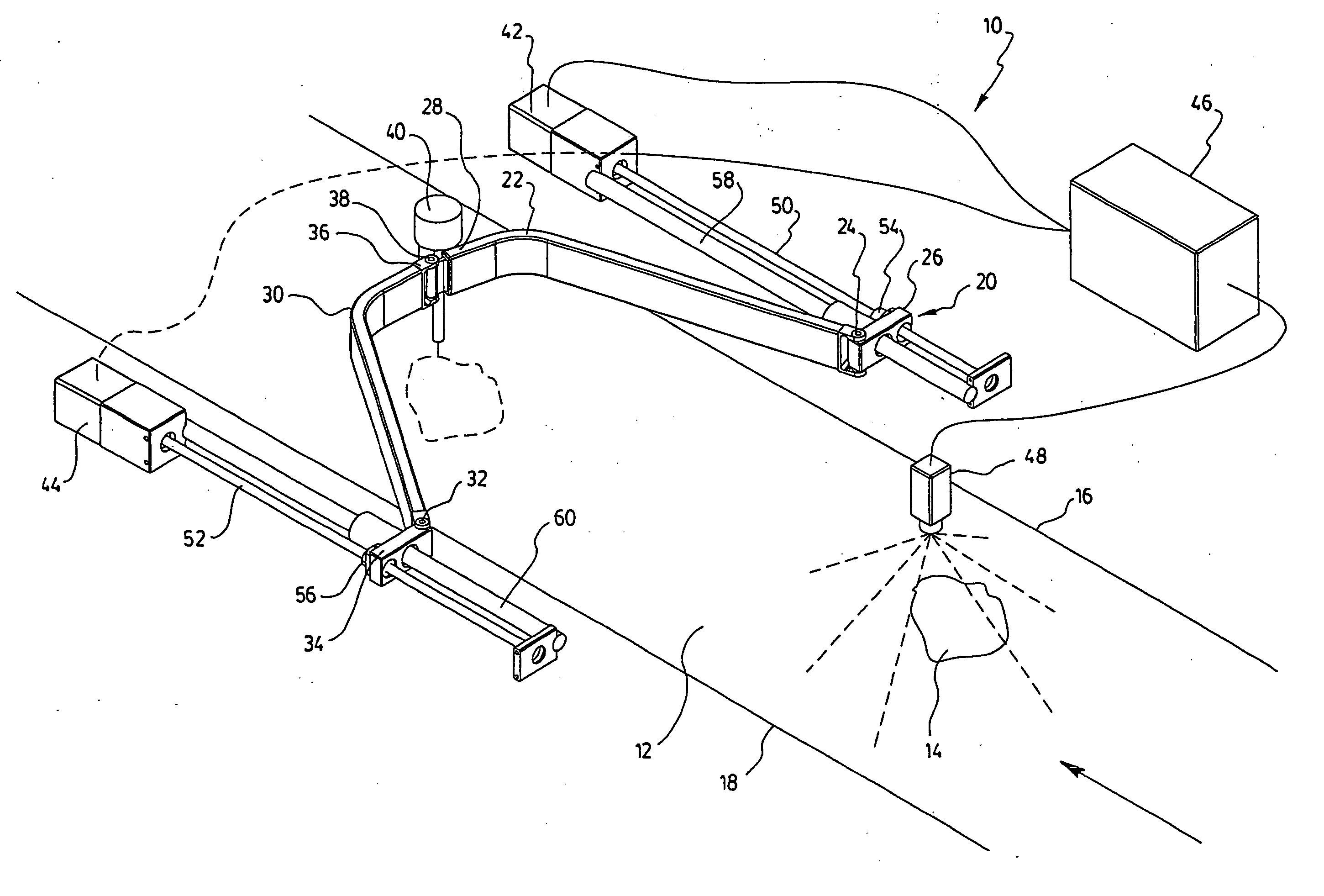
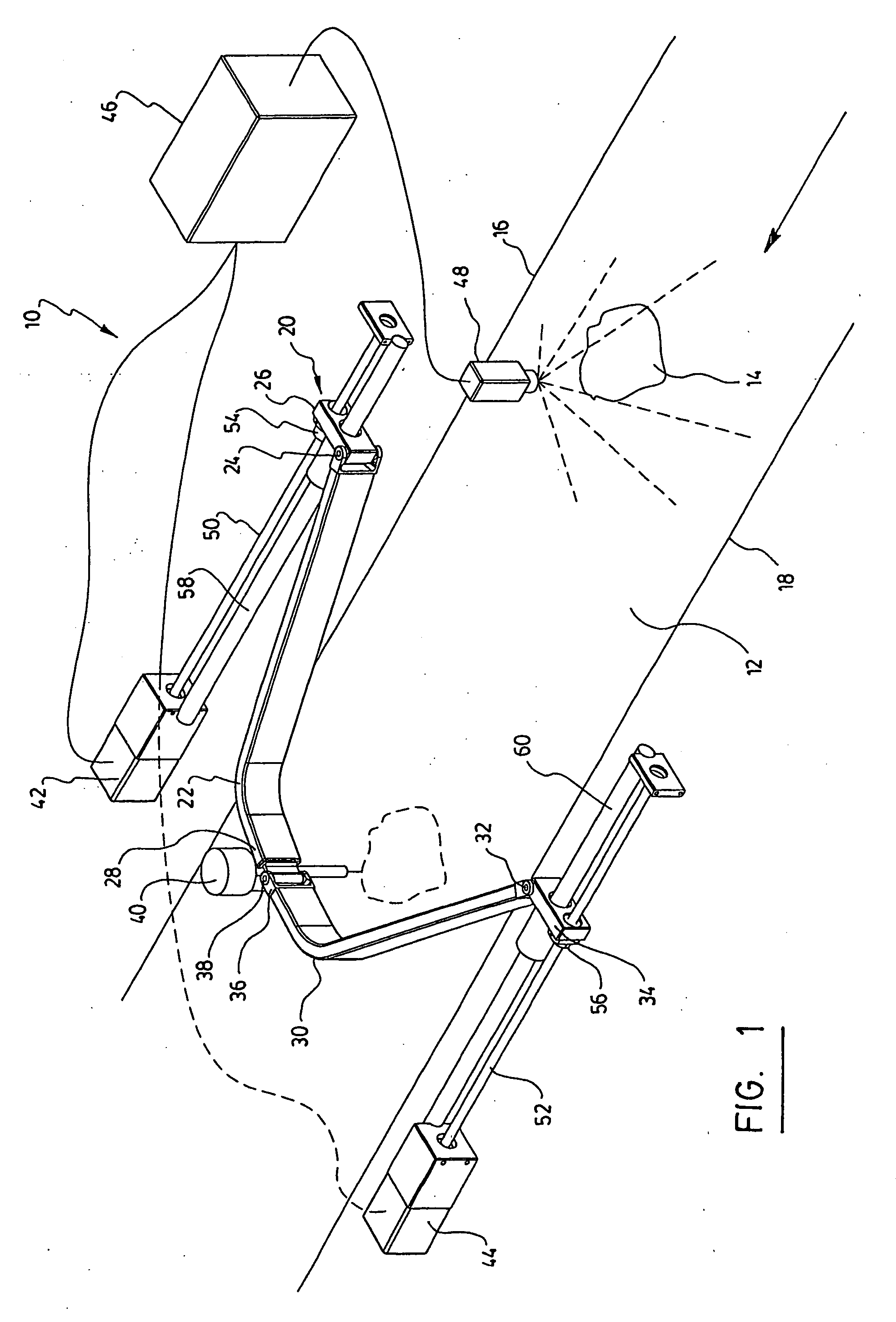
[0051] The planar robot 10 for cutting products according to the preferred embodiment of the invention as shown in FIG. 1, comprises a support structure having an entrance and an exit.

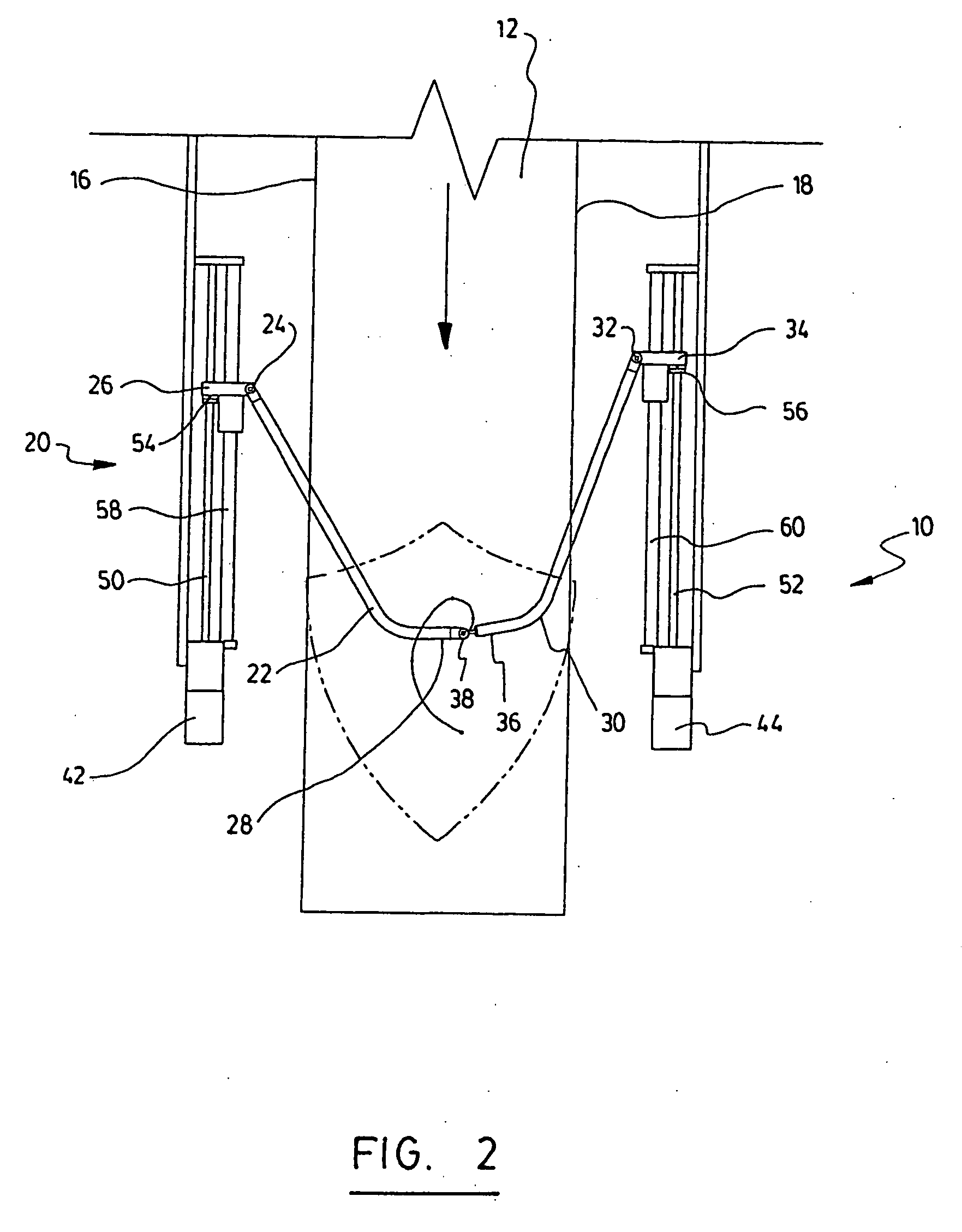
[0052] The robot comprises a conveyor 12 extending within the support structure for transporting the products 14 to be cut from the entrance to the exit of the conveyor. As shown, the conveyor 12 has a first side 16 and a second side 18 opposite the first side 16.

[0053] The robot also comprises at least one cutting module 20. This cutting module 20 as it is illustrated, comprises a first generally L-shaped arm 22 extending above the conveyor 12.

[0054] The first arm 22 comprises a first extremity 24 pivotally mounted on a first mobile base 26, the first mobile base 26 being connected to the support structure on the first side 16 of the conveyor 12. The first arm 22 comprises also a second extremity 28.

[0055] The cutting module 20 comprises a second generally L-shaped arm 30 standing above the convey...


PUM

PropertyMeasurementUnit
Displacementaaaaaaaaaa

Abstract

A planar robot for cutting products, such as pieces of meat. The product is displaced along a conveyor or positioned onto a working table and is cut by a tool, preferably a water jet. The tool is held by a pair of arms. The arms have first extremities pivotally mounted on mobile bases. The arms also have second extremities pivotally connected to each other. An actuator displaces each of the mobile bases in order to control the position of the cutting tool in a plane above the conveyor or table.

Description

FIELD OF THE INVENTION [0001] The present invention relates to a planar robot. More particularly, it relates to a planar robot especially adapted for cutting products transported on a conveyor or positioned onto a working surface, such as a fixed table. BACKGROUND OF THE INVENTION [0002] In the prior art, there exist different types of systems for cutting products transported on a conveyor. [0003] For example, Canadian patent no. 1,307,719 belonging to DSI discloses an apparatus and a method for automatic cutting food products. The apparatus comprises a conveyor on which the products to be cut are displaced. The apparatus also comprises means to determine the dimension of the products to be cut. The apparatus further comprises a cutting tool that can travel in a transverse manner with respect to the displacement of the conveyor. [0004] Prior art systems are interesting but often have high inertias in the mechanisms required for the transverse cutting. [0005] Prior art systems are al...

Claims


Application Information

Patent Timeline
IPC IPC(8): B26D5/20B26F3/00
CPCA22C17/0006Y10T83/173Y10T83/364Y10T83/647Y10T83/6875
Inventor LACHANCE, CHRISTIAN
Owner G E LEBLANC
Why Eureka
Try Eureka