
Microwave antenna for medical ablation

Inactive Publication Date: 2006-12-28
UNIV OF TECH SYDNEY +1
View PDF15 Cites 96 Cited by
  • Summary
  • Abstract
  • Description
  • Claims
  • Application Information

AI Technical Summary

Benefits of technology

[0015] Appropriate impedance matching not only minimises reflections, but also sets up standing waves in the antenna element that assist in producing a near-field having high power.
[0029] It is an advantage of this slot configuration is that the length of the antenna element can be lengthened or shortened while maintaining a uniform near-field distribution, making it ideal for creating linear lesions for the treatment of atrial fibrillation.
[0030] The dielectric loading produced by the size of the insulator surrounded by the cap may be optimized to ensure the near-field terminates at the tip of the antenna rather than at the transmission line / antenna element junction. This prevents heating of the transmission line during the ablation procedure.
[0039] The shape of this antenna determines the shape of the near-field. The near-field terminates at both the tip of the antenna and the antenna element / transmission line junction. When in situ within a vein, unwanted heating of the transmission line / antenna element junction is reduced by the cooling effect of blood flow.
[0040] The antenna may further comprise a Teflon sheath surrounding at least the antenna element. This ensures electrical safety and biocompatibility.
[0047] One of the many advantages of tissue ablation using energy at microwave frequencies is that the microwave energy can be delivered to the myocardium without physical contact between the antenna and the myocardium.

Problems solved by technology

This can result from an irritable focus in the atrium, the AV node, the HIS bundle, or the ventricles.
If a patient goes into atrial fibrillation after a heart attack, the likelihood of fatality doubles.
Furthermore, these patients may suffer adverse and sometimes life threatening side effects as a result of the medication.
This approach requires general anesthesia and can rupture certain cardiac tissues.
However, RF energy has several limitations including the rapid dissipation of energy in surface tissues resulting in shallow lesions and failure to access deeper arrhythmic tissue.
Another limitation is the risk of clots forming on the energy emitting electrodes.
The use of optical and ultrasound energy as ablation sources has also been investigated with limited success.
However, it has proved to be extremely difficult to treat atrial arrhythmias using catheter ablation since it is necessary to produce linear lesions sufficiently long and deep to provide an isolating channel between two conducting nodes.
This will cause recurrence of the arrhythmia after the procedure.

Method used


Image

  • Microwave antenna for medical ablation
  • Microwave antenna for medical ablation
  • Microwave antenna for medical ablation

Examples


Embodiment Construction

The Coaxial Ring Slot Array (CRSA) Antenna

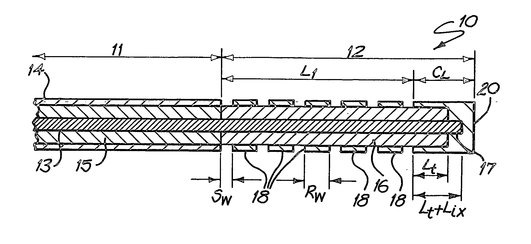
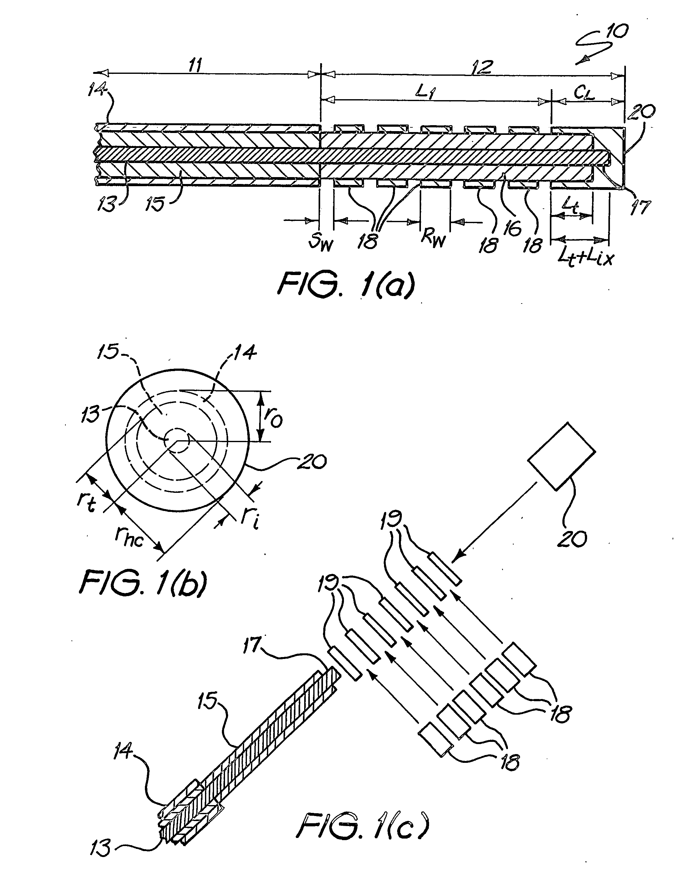
[0079]FIG. 1 shows the configuration of the coaxial ring slot array (CRSA) antenna 10 for cardiac ablation. The antenna 10 has a coaxial cable transmission line 11 and an antenna element 12 formed at the distal end of the transmission line 11. The coaxial cable comprises an inner conductor 13, an outer conductor 14 and a Teflon dielectric insulator 15 which provides insulation between the inner 13 and the outer 14 conductors. The insulator 15 has a diameter of about 3 mm, and the conductors about 0.91 mm.

[0080] the antenna element 12 is constructed out of the distal end of the transmission line by first removing the outer conductor 14 of the coaxial cable for the length L1+l+Lix, exposing a sheath 16 of insulator 15. At the distal end of the antenna element 12 a short length Lis of the Teflon insulation sheath 16 is removed exposing an equally short length 17 of the inner conductor 13. Copper rings 18 are made from copper tubes with a dia...


PUM


Abstract

A microwave antenna suitable for cardiac ablation, in particular for catheter ablation, and a method for making such an antenna. The antenna comprises a transmission line having an inner conductor, an outer conductor, and a dielectric insulator to provide insulation between the inner and outer conductors. An energy emitting antenna element is located at the distal end of the transmission line. The antenna element has an inner conductor which is electrically coupled to the inner conductor of the transmission line, and, around the inner conductor, a sheath of dielectric insulator continuous with the insulator of the transmission line. At its distal end, a hollow metallic cap is electrically connected to the inner conductor, surrounding a length of the insulator.

Description

TECHNICAL FIELD [0001] This invention concerns a microwave antenna for medical ablation. In particular it concerns such an antenna suitable for cardiac ablation. In a further aspect it concerns a method for making such an antenna. BACKGROUND ART [0002] The heart is composed of three types of cardiac tissue, atrial muscle, ventricular muscle and specialized excitatory and conduction tissues. The atrial and ventricular muscles of the heart are normally excited synchronously. Each cardiac cycle begins with the generation of action potentials by the sino-atrial (SA) node located in the posterior wall of the right atrium. These action potentials spread through the atrial muscle by means of specialized conduction tissue, causing contraction. The action potentials do not normally spread directly from the atrial muscles to the ventricular muscle. Instead, the action potentials conducted in the atrial musculature reach the atrioventricular (AV) node and its associated fibres, which receive a...

Claims


Application Information

Patent Timeline
IPC IPC(8): H05B6/72A61B17/00A61B18/18A61N5/02
CPCA61B18/18A61B18/1815A61B2018/1861A61B2018/00375A61B2017/00243
Inventor CHIU, HENG-MAOSANAGAVARAPU, ANANDA MOHANTHOMAS, STUART PHILIPROSS, DAVID LESLIEGUY, DUNCAN JAMES RAMSAY
Owner UNIV OF TECH SYDNEY
Learn More