Optical switch device and optical switching method
a technology of optical switch and optical switch, which is applied in the direction of optics, electrical appliances, instruments, etc., can solve the problems of loss of linearity of optical response, inability to increase the extinction ratio (the ratio of the maximum to the minimum intensity of transmitted light) and the likelihood of lowering the signal level
- Summary
- Abstract
- Description
- Claims
- Application Information
AI Technical Summary
Benefits of technology
Problems solved by technology
Method used
Image
Examples
first embodiment
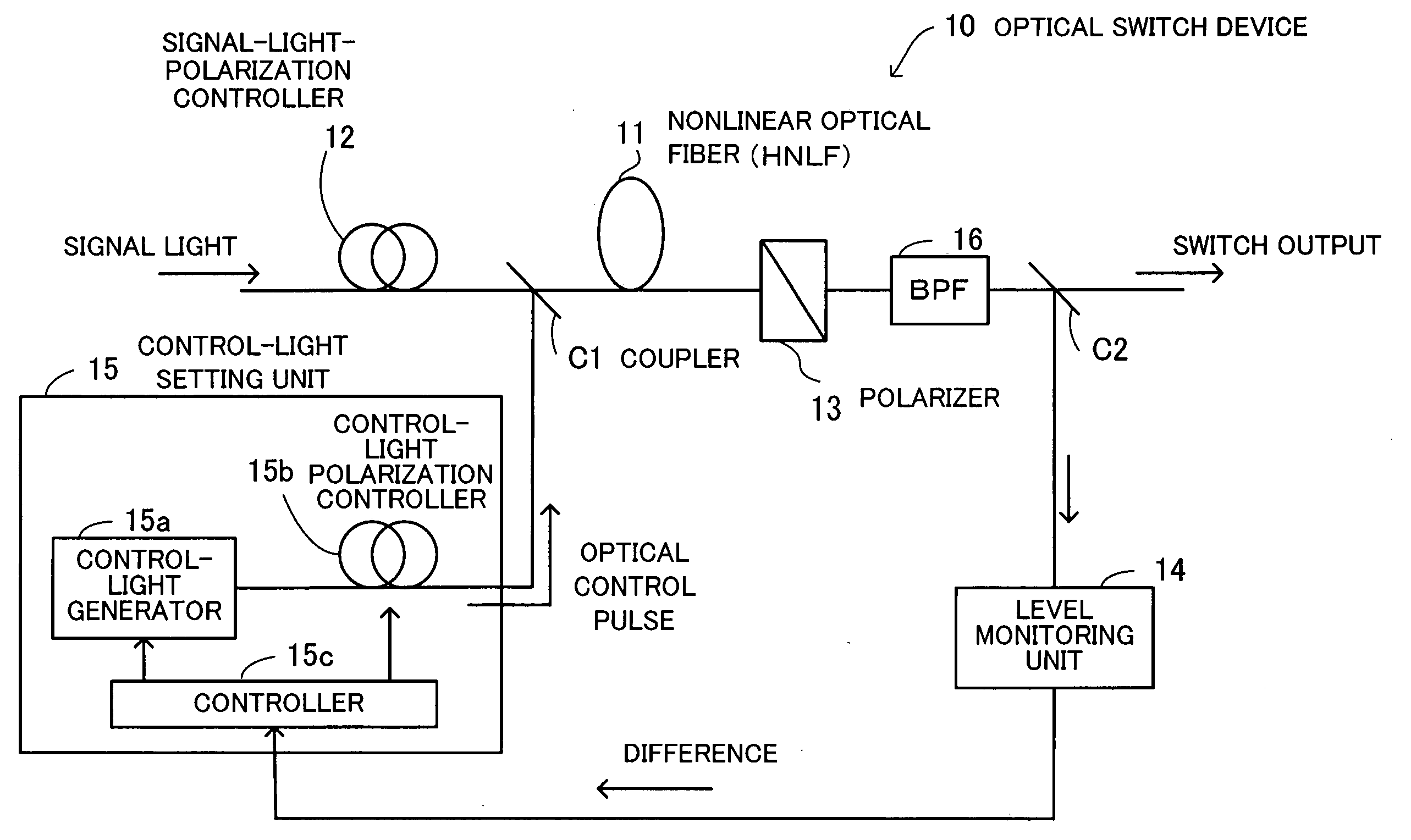
[0113] First, exemplary sequences of operations of the optical switch device are explained below.
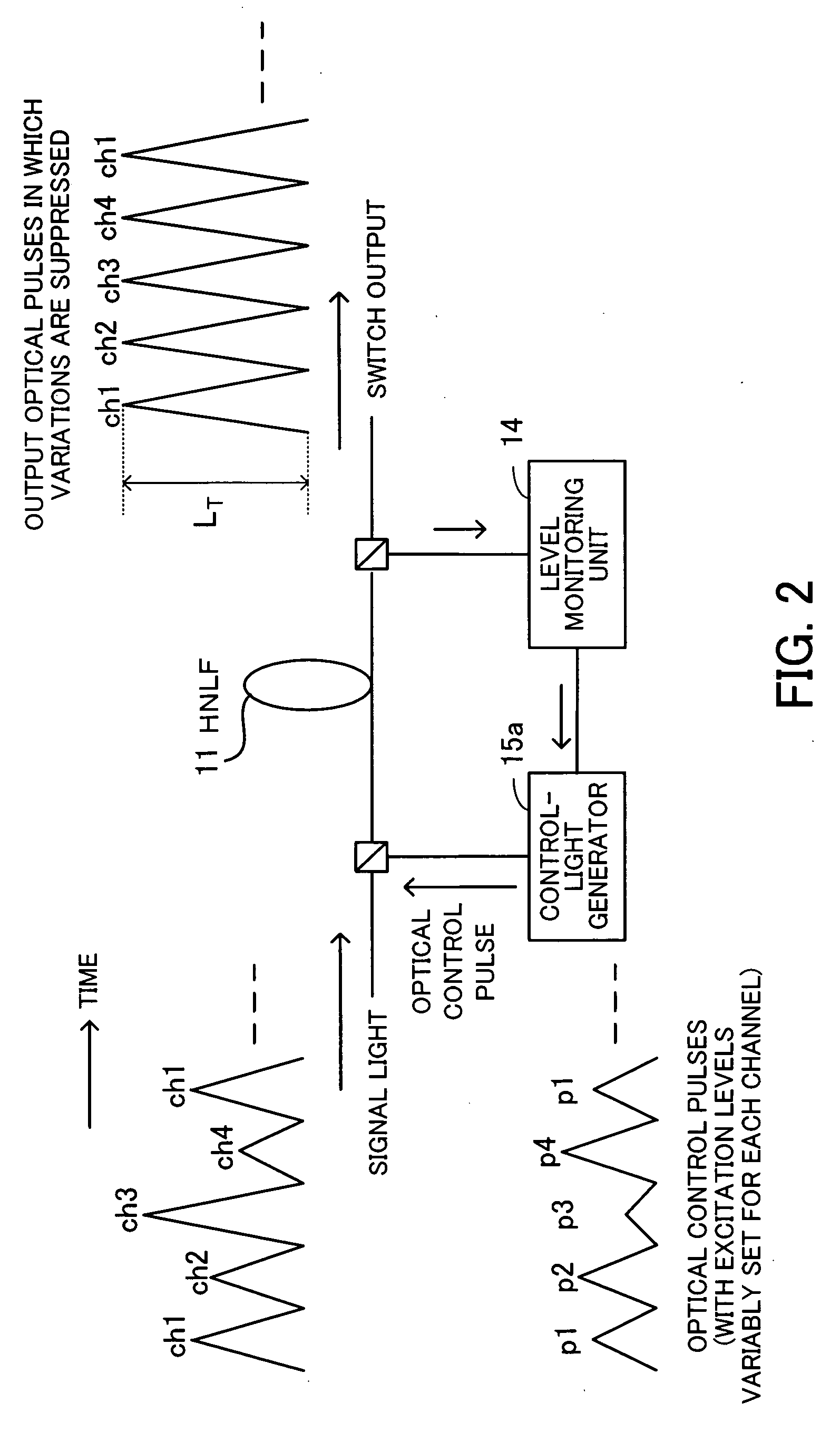
[0114]FIG. 7 is a flow diagram indicating a first exemplary sequence of operations of the optical switch device according to the first embodiment. The sequence of FIG. 7 also corresponds to the operations which are explained before with reference to FIG. 2.
[0115]1> The control-light generator 15a generates optical control pulses p1 with their initial levels set to X1, and inputs the optical control pulses p1 into the HNLF 11 at the same timings as optical pulses of the signal light in the channel ch1. At this time, the levels of the optical control pulses p2 to p4 are set to zero.
[0116]2> The level monitoring unit 14 receives through the coupler C2 the optical pulses of the signal light in the channel ch1 outputted from the filter 16, performs opto-electric (O / E) conversion of the received optical pulses, and monitors the levels of the received optical pulses. When the monitored level...
second embodiment
[0143] Next, exemplary sequences of operations of the optical switch device are explained below.
[0144] According to the first embodiment, the levels of the optical control pulses for each channel are set in succession while the levels of the optical control pulses for the other channels (which may include one or more channels in which the levels of the optical control pulses are already set) are maintained at zero. That is, each channel is not in operation until the setting of the levels of the optical control pulses for all the channels is completed. On the other hand, according to the second embodiment, the levels of the optical control pulses for each channel are set in succession while one or more other channels in which the levels of the optical control pulses have already been set are in operation.
[0145] According to the second embodiment, first, the levels of the optical control pulses p1 in the channel ch1 (as a first one of the channels) are set so as to bring the output ...
third embodiment
[0184] Hereinbelow, operations for controlling the levels of optical pulses outputted from the optical switch device are explained.
[0185] According to the third embodiment, a low-frequency signal is superimposed on optical control pulses so as to realize intensity modulation (amplitude modulation), and the intensity-modulated optical control pulses are inputted into the HNLF 11. Then, the levels of the optical control pulses for use in excitation in each channel are feedback controlled on the basis of the amplitude of a low-frequency signal superimposed on optical pulses which are intensity-modulated, switched, and outputted, so that the optical pulses outputted after switching are controlled at a desired level.
[0186]FIG. 13 is a diagram illustrating an outline of operations performed by the optical switch device according to the third embodiment of the present invention.
[0187]41> A superimposed signal p1a is generated by superimposing a low-frequency signal on optical control pu...
PUM
| Property | Measurement | Unit |
|---|---|---|
| length | aaaaa | aaaaa |
| angle | aaaaa | aaaaa |
| rotation angle | aaaaa | aaaaa |
Abstract
Description
Claims
Application Information
 - R&D
- Intellectual Property
- Life Sciences
- Materials
- Tech Scout
- Unparalleled Data Quality
- Higher Quality Content
- 60% Fewer Hallucinations
Browse by: Latest US Patents, China's latest patents, Technical Efficacy Thesaurus, Application Domain, Technology Topic, Popular Technical Reports.
© 2025 PatSnap. All rights reserved.Legal|Privacy policy|Modern Slavery Act Transparency Statement|Sitemap|About US| Contact US: help@patsnap.com


