Current Collector Structure and Methods to Improve the Performance of a Lead-Acid Battery

a current collector and lead-acid battery technology, applied in the field of current collectors, can solve the problems of limiting the actual specific energy of a lead-acid battery, imposing challenging performance demands on battery technology, and low utilization efficiency of active mass, so as to enhance the cyclability of the subsequent high surface area electrode, the effect of improving the performan

Inactive Publication Date: 2006-12-28
GYENGE ELOD +2
View PDF6 Cites 46 Cited by
  • Summary
  • Abstract
  • Description
  • Claims
  • Application Information

AI Technical Summary

Benefits of technology

[0005] The present invention relates to methods of improving the performance, especially cycling performance, of batteries by using current collector structures based on light-weight, porous, open pore, high specific surface area (e.g. >500 m2 / m3) reticulated substrates, such as, for example, a foam substrate, at least partially coated with a metal alloy. More specifically it relates to the use of metal alloys deposited on lightweight, open pore substrates such as carbon foam or aluminum foam to dramatically enhance the cyclability of the subsequent high surface area electrode for use as a positive and / or negative electrode in lead acid batteries.

Problems solved by technology

Continuous developments on the application side, for instance in the area of electric vehicles and hybrid electric vehicles (EV and HEV), impose challenging performance demands on battery technologies in general and lead acid batteries in particular.
The low utilization efficiency of the active mass, especially on the positive electrode, in conjunction with the heavy weight of the lead current collectors, limits the actual specific energy of a lead-acid battery.

Method used


Image

  • Current Collector Structure and Methods to Improve the Performance of a Lead-Acid Battery
  • Current Collector Structure and Methods to Improve the Performance of a Lead-Acid Battery
  • Current Collector Structure and Methods to Improve the Performance of a Lead-Acid Battery

Examples


Embodiment Construction

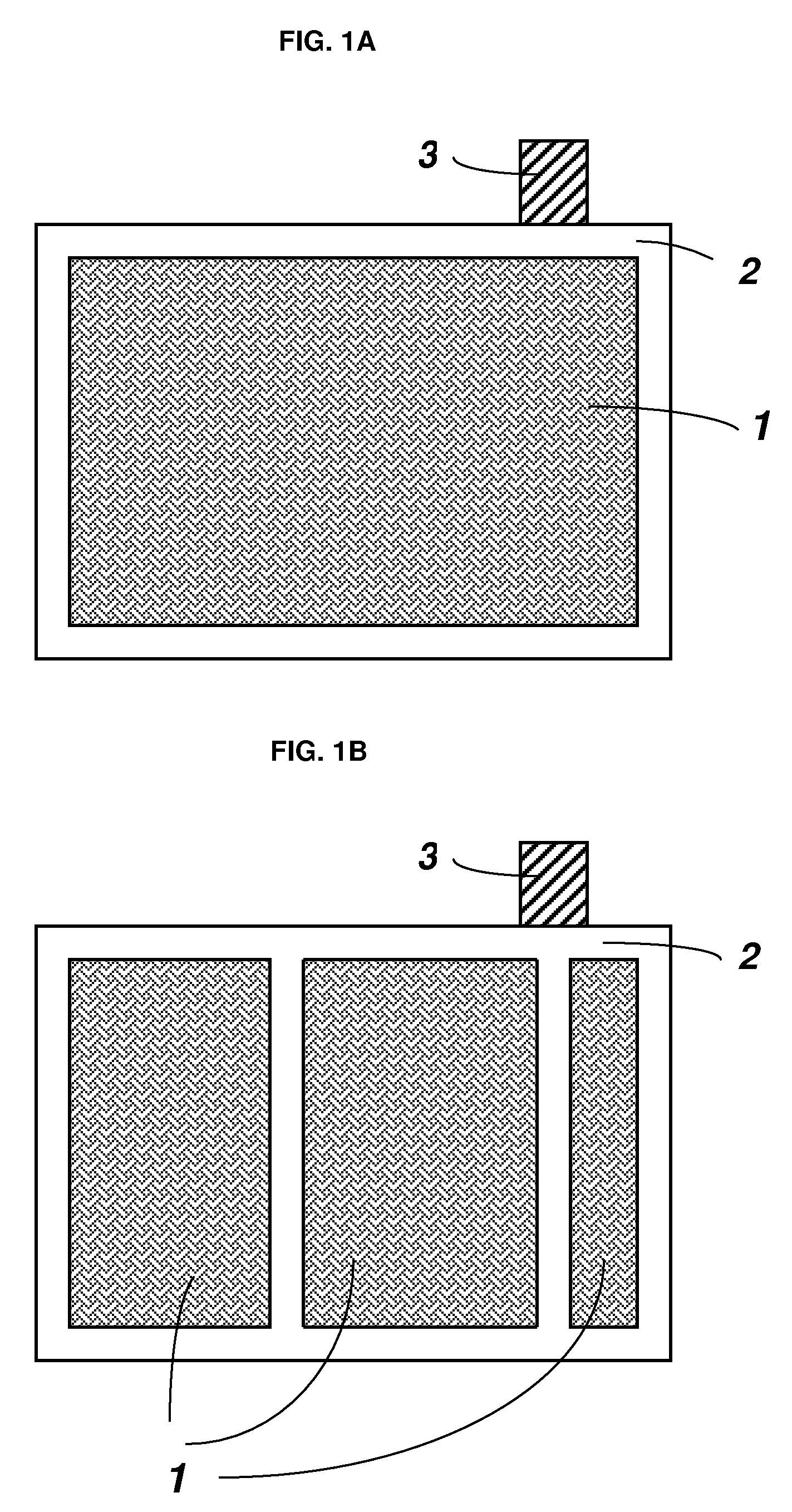
[0026]FIG. 1A represents a front view of the current collector structure according to one embodiment of the present invention. Denoted by reference numeral 1 is the high specific surface area reticulated substrate. In one embodiment, a metal layer is deposited on all or a portion of the substrate. For example, lead or lead-alloys may be deposited on the electrically conductive, reticulated substrate, which may be reticulated vitreous carbon. The high specific surface area part is attached to a frame 2, which in turn is connected to a lug or tab 3. Both the frame 2 and tab 3 may be made of lead, a lead-alloy or other metal alloy.

[0027] In another embodiment, shown by FIG. 1B, the reticulated part 1 is compartmentalized by intercalated strips or other structural members which are part of the overall frame structure 2. The compartmentalization can improve the current and potential distribution characteristics across the high specific surface area component of the current collector str...


PUM

PropertyMeasurementUnit
specific energyaaaaaaaaaa
thicknessaaaaaaaaaa

Abstract

A current collector of a battery includes a reticulated substrate having a circuitous network of pores and a metal applied to at least a portion of the reticulated substrate. The reticulated substrate may be a non-metal foam substrate, such as, for example, a carbon foam substrate, a reticulated vitreous carbon substrate or a graphite foam substrate.

Description

CROSS-REFERENCE TO RELATED APPL1ICATIONS [0001] This utility patent application is a continuation of co-pending U.S. patent application Ser. No. 11 / 279,103 filed on Apr. 8, 2006 and 11 / 048,104 filed on Feb. 2, 2005, which were co-pending with application Ser. No. 10 / 809,791 filed on Mar. 26, 2004, which was co-pending with PCT / US2002 / 30607 filed on Sep. 25, 2001, which was co-pending with and claims the benefit of United States Provisional Application 60 / 325,391 filed Sep. 26, 2001, which are all incorporated by reference herein.FIELD OF THE INVENTION [0002] This invention relates generally to electrodes and particularly to high surface area electrodes which improve the performance of batteries in one or more ways alone or in combination such as: specific discharge capacity, positive active mass utilization, and discharge / recharge cyclability. BACKGROUND OF THE INVENTION [0003] Batteries have been used for diverse applications such as starting-lighting-ignition (SLI), uninterrupted ...

Claims


Application Information

Patent Timeline
Patent Type & Authority Applications(United States)
IPC IPC(8): H01M4/80
CPCC25D3/56C25D7/00H01M4/14Y02E60/126H01M4/667H01M4/80H01M4/663Y02E60/10
Inventor GYENGE, ELODJUNG, JOEYSNAPER, ALVIN A.
Owner GYENGE ELOD
Why Eureka
Try Eureka