
Apparatus and methods for dispensing fluidic or viscous materials

Inactive Publication Date: 2007-01-04
RHINO LININGS CORP
View PDF47 Cites 91 Cited by
  • Summary
  • Abstract
  • Description
  • Claims
  • Application Information

AI Technical Summary

Benefits of technology

[0039] In a seventh aspect of the invention, business methods allowing for reduced inventory and manufacturing burden relating to the aforementioned dispensing systems are disclosed.

Problems solved by technology

As with the invention of Franklin, et al. described above, the apparatus is complex, and includes many chambers and passageways that render it difficult to purge and clean after use or when switching constituent mixing components (e.g., changing colors).
Despite the foregoing broad range of solutions to mixing and metering fluid / viscous components, all generally suffer from several salient deficiencies, including most notably: (i) the need for separate metering controls that are precisely adjusted in order to maintain the desired mixture ratio(s) of the constituents; (ii) use of mixing tanks, lines, etc., which must be thoroughly purged (usually at significant cost and expenditure of time and effort) before a different mixture (e.g., colors) can be used; purging of these prior art systems also requires use of solvents, which are costly, damaging to the environment if not disposed of properly, and potentially toxic to the operator(s) of the system; (iii) increased size and complexity (relatively speaking), thereby making them difficult to move and manage in confined spaces or situations where only one operator is present; and (iv) use of colorant reservoirs or “paint pots” that must be kept in a specific orientation (e.g., vent side up), and maintained vented to the atmosphere (the latter which causes some degree of unwanted curing or hardening of the material due to interaction with atmospheric gases and moisture).
Under existing prior art approaches, excessive waste and costly cleanup procedures characterize the main difficulties in combining and changing the colorant(s) used with reactive components.
During long periods of time without mixing, the colorant, which tends to be much heavier and more viscous than the polyol, tends to clog the passageways of the system, especially on the vacuum side of the system.
Because of this requirement there is often a significant waste that results via this “batch” method.
Also, changing colors is made difficult when using this method since there is a need to empty and clean the storage container and any exposed system passageways prior to each color change.
5000 cps or higher) this task is almost never accomplished thoroughly, creating a real challenge of matching both standard and custom colors since there is almost invariably contamination of the new color from one (or more) of the colors previously used within that system.
Other prior art methods do not “pre-mix” the colorant and polyol, but rather maintain the colorant in a “paint pot” or hopper.
The process of filling colorant into a paint pot / hopper none-the-less creates significant cleaning difficulties, and requires an operator to perform numerous steps in order to prepare the system to apply a colored polyurethane coating.
This system remains largely inefficient because: (i) much of the colorant removed from the lines cannot be reclaimed, (ii) a significant quantity of solvent is needed to flush and clean the lines, such solvent presenting both a health hazard to the operator(s) and an environmental hazard, and (iii) trained operators are required, and must follow a specific procedure and sequence of steps in order to properly flush the system.
In addition, any solvent residues that remain in the line(s) after flushing the system can subsequently result in uncontrolled reactions with the multi-component materials in a later application.
These reactions could result in inconsistencies in the color of the colorant being applied, and / or negatively impact the reaction between the components during application (and even its physical properties after application and curing).
Also, because the colorant added to the reservoir and any reclaimed colorant after use would inherently be exposed to the atmosphere, the colorant may absorb unwanted humidity, and react with atmospheric gases (including hardening or “skinning over”), thereby potentially affecting the reaction between the other constituent components or the efficacy of the colorant itself.
This added complexity is costly (requiring, e.g., multiple independent yet communicative controllers and circuitry), and generally provides for a system susceptible to both significant variations in metering (lack of precision) and failure.
Such techniques also may require frequent adjustment due to changes in the density and / or temperature of the material(s) being metered, variations in atmospheric pressure, etc.

Method used


Image

  • Apparatus and methods for dispensing fluidic or viscous materials
  • Apparatus and methods for dispensing fluidic or viscous materials
  • Apparatus and methods for dispensing fluidic or viscous materials

Examples


Embodiment Construction

[0050] Reference is now made to the drawings wherein like numerals refer to like parts throughout.

[0051] As used herein, the term “pump” refers to any motive source capable of physically moving a material such as, without limitation, a fluid or viscous material.

[0052] As used herein, the term “positive displacement pump” refers to a type of pump which, for example, forces a material (e.g., fluid) from one chamber to another by reducing the volume of a first chamber while simultaneously increasing the volume of a second. These types of pumps produce constant measured flow of fluid over a wide range of pressures at either the input port or output port. Examples of positive displacement pumps include, but are not limited to, progressive cavity (e.g., screw), gear, lobe, piston, or peristaltic pumps.

[0053] As used herein, the term “reactive mixture” refers to any multi-component reactive mixture where each individual component, when mixed, result in a chemical reaction whereby the su...


PUM

PropertyMeasurementUnit
viscousaaaaaaaaaa
motive forceaaaaaaaaaa
flexibleaaaaaaaaaa

Abstract

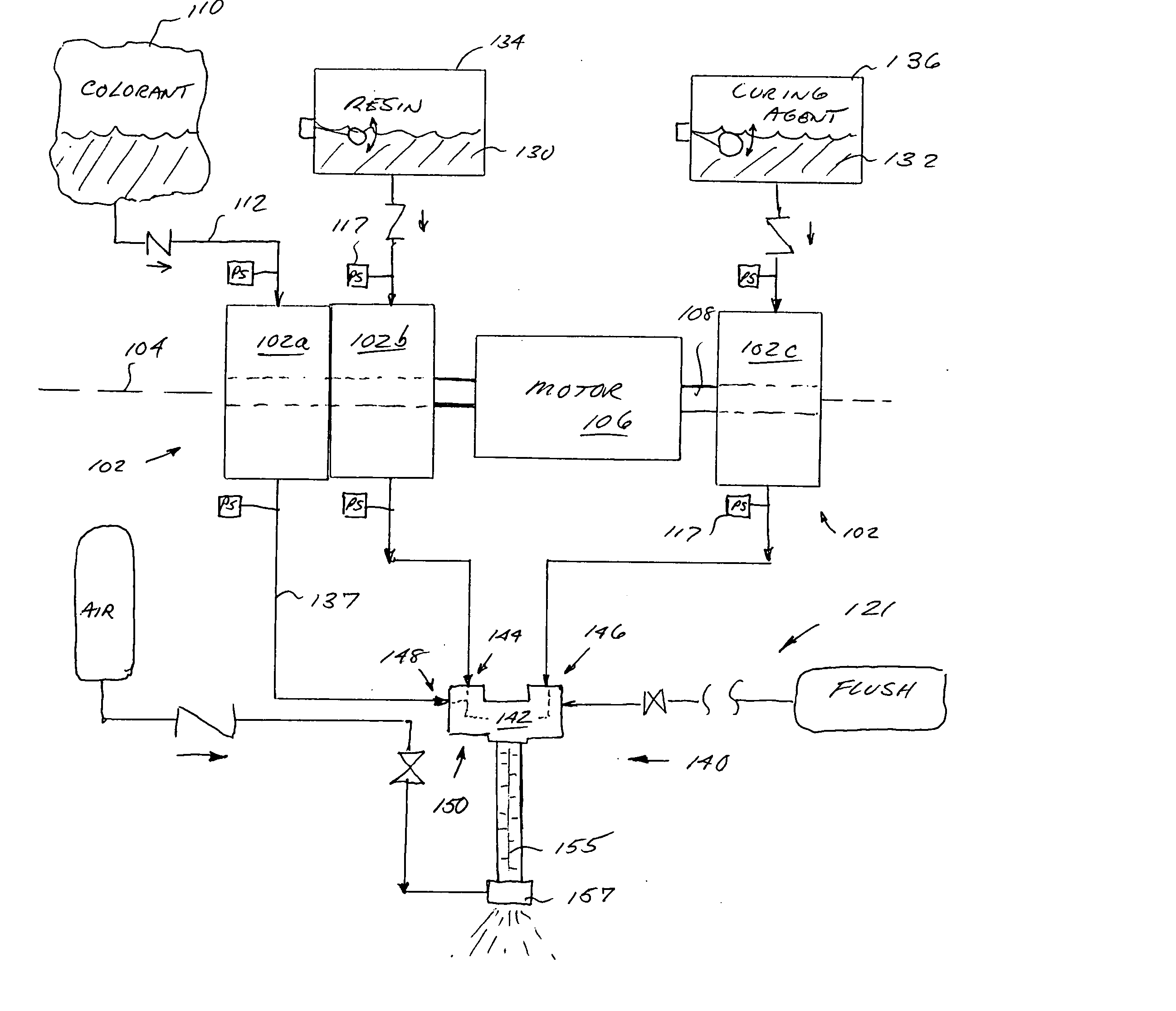
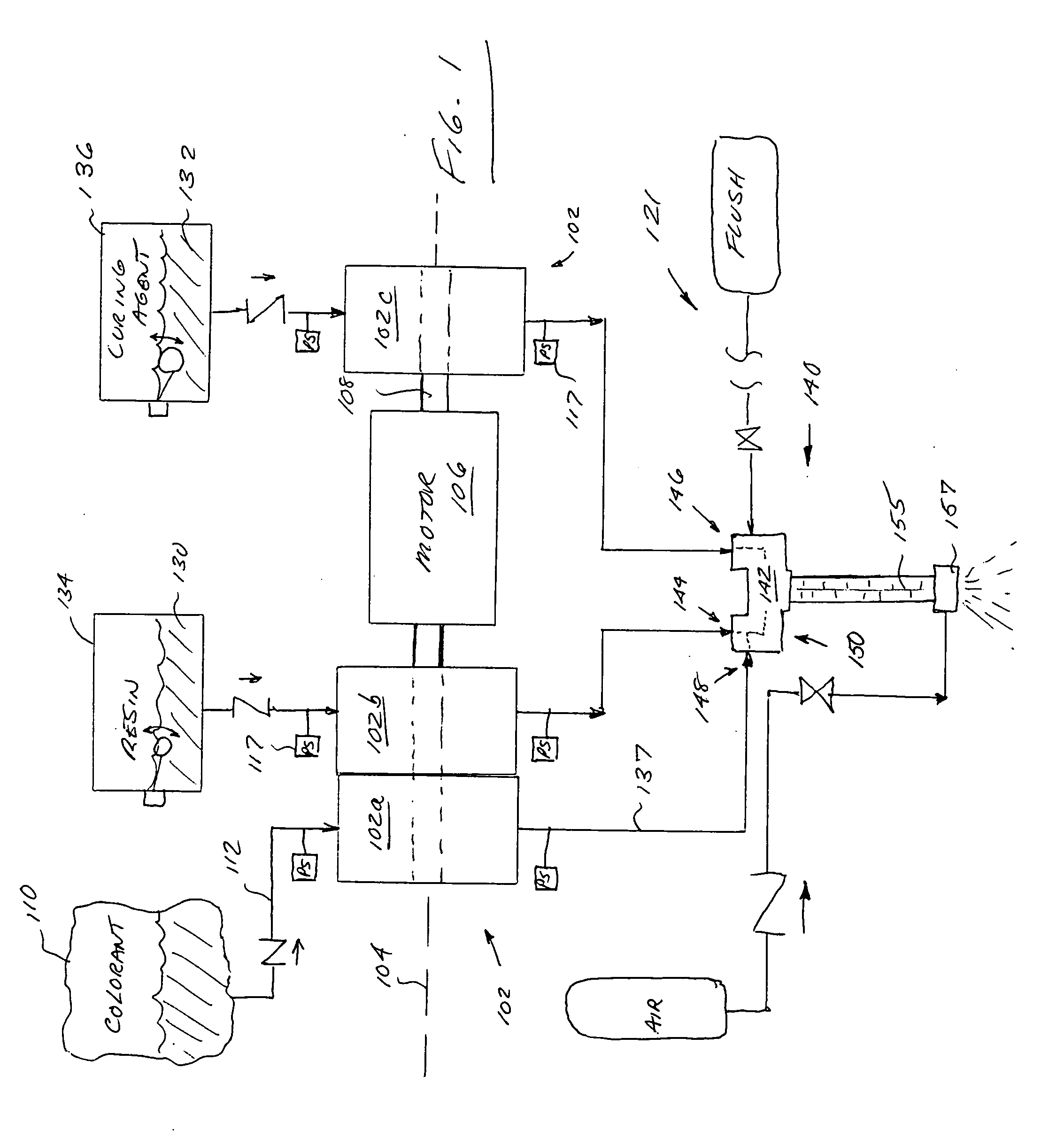
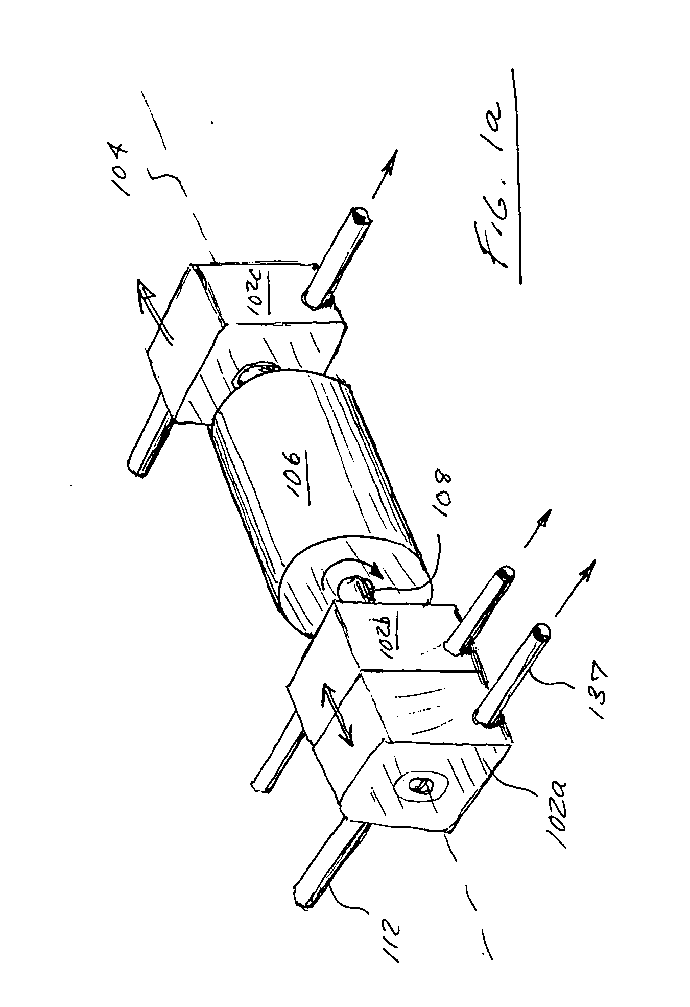
Mixing and dispensing apparatus and methods for use with, e.g., a multi-component reactive material process is disclosed. In one embodiment, the apparatus comprises a series of positive displacement pumps adapted for stacked or “piggy-back” mating to a common motive source. At least one of the pumps is supplied by a sealed and collapsible reservoir bag and flexible tubing, thereby allowing removal (and optionally disposal) of one or more complete material pathways within the system. Such a configuration allows for, inter alia, rapid colorant changing with minimal material waste, obviates the use of hazardous solvents, and increases process efficiency and worker productivity. This arrangement also obviates complex metering apparatus common to prior art systems, thereby allowing it to be as small and power / cost efficient as possible.

Description

COPYRIGHT [0001] A portion of the disclosure of this patent document contains material that is subject to copyright protection. The copyright owner has no objection to the facsimile reproduction by anyone of the patent document or the patent disclosure, as it appears in the Patent and Trademark Office patent files or records, but otherwise reserves all copyright rights whatsoever. [0002] 1. Field of the Invention [0003] The present invention relates generally to the field of plural-component coating applications, and in one exemplary aspect to apparatus and methods for metering, mixing and delivering fluidic and / or viscous materials. [0004] 2. Description of Related Technology [0005] A variety of different techniques for mixing and metering fluid and / or viscous components (such as reactive polymers used in applying coatings) are known in the prior art. For example, U.S. Pat. No. 2,847,196 to Franklin, et al., discloses one such arrangement generally representative of the prior art. ...

Claims


Application Information

Patent Timeline
Patent Type & Authority Applications(United States)
IPC IPC(8): B67D5/60B67D5/52B67D7/70B67D7/78
CPCB01F15/042B01F13/1055B29B7/325B29B7/603B01F33/84B01F35/8311
Inventor LEWIS, RUSSELL H.SOLOMON, MIHAI A.
Owner RHINO LININGS CORP
Learn More