Energy storage system for powering vehicle electric user devices

Inactive Publication Date: 2007-01-04
FAB ITAL MAGNETI MARELLI SPA +1
View PDF9 Cites 34 Cited by
  • Summary
  • Abstract
  • Description
  • Claims
  • Application Information

AI Technical Summary

Benefits of technology

[0011] It is an object of the present invention to provide an energy storage system, for powering vehicle electric user devices, designed to eliminate the aforemen

Problems solved by technology

Both these problems are of universal concern, and there is not a car industry that is not currently engaged in researching and developing vehicles capable of providing at least partial solutions and reducing the effect these problems have on human living conditions.
During start-up, the electric starter motor consumes a considerable amount of electrical energy, thus greatly stressing and reducing the electric charge of the vehicle battery.
In “Stop and Start” mode, therefore, intensive use is made of the vehicle battery, on account of the high frequency with which the internal combustion engine is started, particularly when driving in city traffic.
Regenerating mode also increases stress of the vehicle battery, on account of the battery having to absorb a large amount of electrical

Method used


Image

  • Energy storage system for powering vehicle electric user devices
  • Energy storage system for powering vehicle electric user devices
  • Energy storage system for powering vehicle electric user devices

Examples


Embodiment Construction

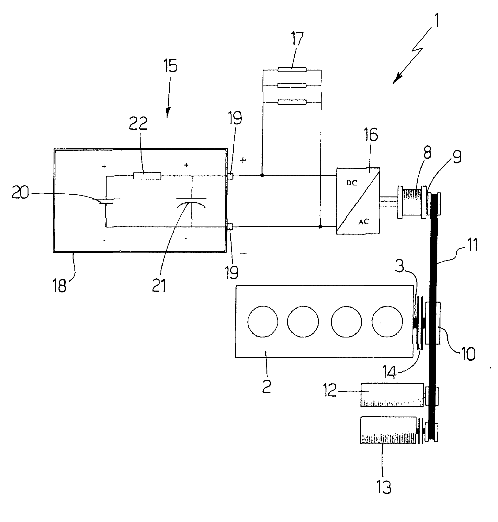
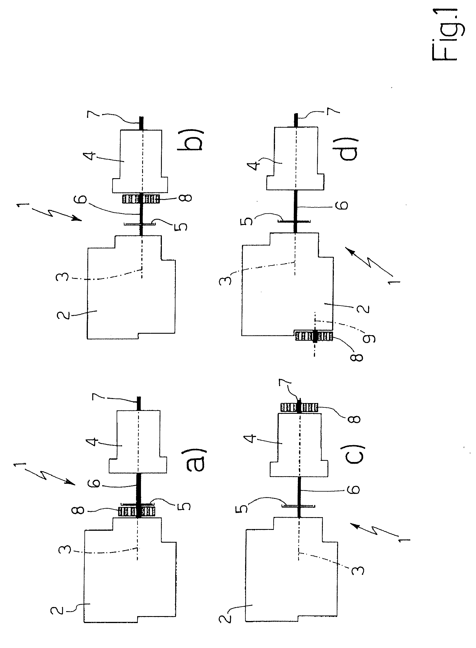
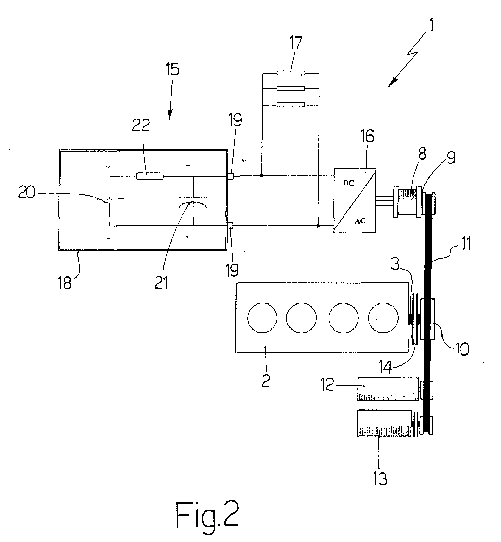
[0023] Number 1 in FIG. 1 indicates as a whole a power train of a hybrid vehicle (not shown). Power train 1 comprises an internal combustion engine 2 having a drive shaft 3 connected to a transmission 4 with the interposition of a clutch 5; transmission 4 has an input shaft 6 connected mechanically to drive shaft 3 with the interposition of clutch 5, and an output shaft 7 connected mechanically to the drive wheels (not shown) of the hybrid vehicle; and power train 1 also comprises a reversible electric machine 8 which may operate as both an electric motor and an electric generator.

[0024] In different embodiments, reversible electric machine 8 is fitted to drive shaft 3 of internal combustion engine 2 upstream from clutch 5 (FIG. 1a), is fitted to input shaft 6 of transmission 4 downstream from clutch 5 (FIG. 1b), is fitted to output shaft 7 of transmission 4 (FIG. 1c), or is connected to a secondary shaft 9 angularly integral with drive shaft 3 of internal combustion engine 2 (FIG....


PUM


Abstract

An energy storage system for powering electric user devices of a vehicle, the energy storage system having a battery; a capacitive element connected parallel to the terminals of the battery; and an inductive element connected in series to the battery, between the battery and the capacitive element; to effectively regulate power/energy flow between the battery and the capacitive element during transients, the ratio between the capacity of the battery measured in (Ah) and the capacitance of the capacitive element measured in (F) is less than 1, and the ratio between the capacity of the battery measured in (Ah) and the inductance of the inductive element measured in (μH) is less than 1.

Description

[0001] The present invention relates to an energy storage system for powering vehicle electric user devices. [0002] The present invention may be used to advantage in the car industry, to which the following description refers purely by way of example. BACKGROUND OF THE INVENTION [0003] The need for more effective technologic solutions to the problems posed by both private and public passenger transport is now generally acknowledged. In particular, attention is increasingly focused on achieving a substantial reduction in consumption and a real reduction in pollutant and acoustic emissions, especially in urban areas. Both these problems are of universal concern, and there is not a car industry that is not currently engaged in researching and developing vehicles capable of providing at least partial solutions and reducing the effect these problems have on human living conditions. [0004] This explains the increasingly widespread use of innovative vehicles equipped with highly efficient,...

Claims


Application Information

Patent Timeline
IPC IPC(8): B60K1/00H02J7/00G09G3/10
CPCF02N11/003F02N11/04F02N11/0814F02N11/0866Y02T10/48F02N2011/0885F02N2011/0896H02J7/345F02N15/022Y02T10/40
Inventor PUCCETTI, ANGELOPENNESE, MICHELE
Owner FAB ITAL MAGNETI MARELLI SPA
Why Eureka
Try Eureka