High-frequency balun
a high-frequency balun and balun technology, applied in the field of balun, can solve the problem of narrowing the band width of the transmission frequency fsub>0 /sub>
- Summary
- Abstract
- Description
- Claims
- Application Information
AI Technical Summary
Benefits of technology
Problems solved by technology
Method used
Image
Examples
first embodiment
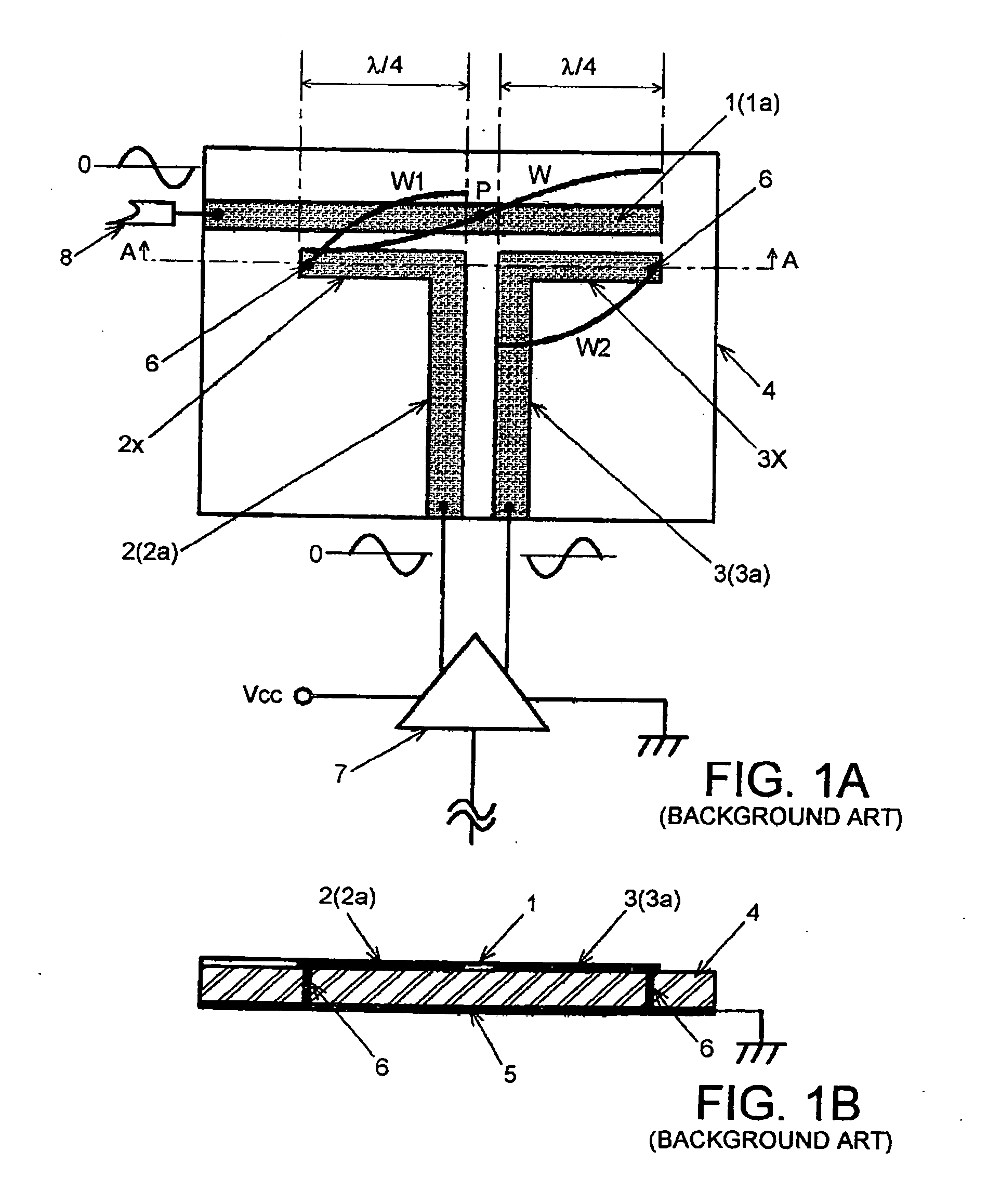
[0043]FIGS. 4A and 4B show a high-frequency balun according to the first embodiment of the present invention. In FIGS. 4A and 4B, the same reference numerals are applied to the same elements as FIGS. 1A and 1B, and no redundant explanations are repeated.
[0044] A balun according to the first embodiment and baluns according to the second and third embodiments, which will be described later, are basically configured by using slot line 9 for converting a balanced line to an unbalanced line and vice versa. A balun according to the first embodiment includes: substrate 4 made of a dielectric material or the like; microstrip lines 10, 11 each having a signal lines formed in one main surface of substrate 4; ground conductor 5 formed on the whole of the other main surface of substrate 4; and slot line 9 arranged by forming an opening in ground conductor 5. Microstrip line 10 is a microstrip line of the unbalanced line for input / output in unbalanced mode. In this specification, we call micros...
second embodiment
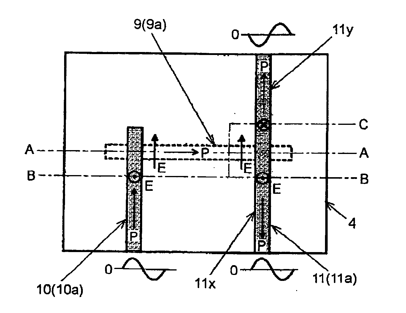
[0052] Next, explanations are given of a balun according to the second embodiment of the present invention with reference to FIGS. 7A to 7c. In FIGS. 7A to 7c, the same reference numerals are applied to the same elements as FIGS. 4A and 4B.
[0053] In the balun according to the first embodiment, one balanced microstrip line 11 is arranged and high-frequency wave components in opposite-phase each other are obtained from both ends of balanced microstrip line 11, whereby the high-frequency component in balanced mode is obtained. However, in the balun according to the second embodiment, a pair, namely, two balanced microstrip lines 11x, 11y are arranged, both balanced microstrip lines 11x, 11y are used as a balanced transmission line as a whole, and a high-frequency component in balanced mode is obtained.
[0054] In the balun according to the second embodiment, the other end portion of unbalanced microstrip line 10 traverses or crosses the center portion (center point) of slot line 9 that...
third embodiment
[0058] A balun according to the third embodiment of the present invention shown in FIG. 8 is similar to that of the first embodiment, however, the balun according to the third embodiment is different from that of the first embodiment in an arrangement for setting the tip portion of unbalanced microstrip line 10 to an electrical short-circuited end and an arrangement for setting both ends of slot line 9 to electric open ends.
[0059] In the third embodiment, the tip end of unbalanced microstrip line 10 projects from the traversing point of slot line 9 is connected to ground conductor 5 by via-hole 6 that is arranged adjacently to the traversing point. Also, both ends of slot line 9 that project from the traversing points of unbalanced microstrip line 10 and balanced microstrip line 11 are formed so as to be wider than the width of slot line 9 in the portion between these two traversing points, that is, the width of aperture line 9a in ground conductor 5. In this embodiment, both ends ...
PUM
 Abstract
Description
Claims
Application Information
 - R&D
- Intellectual Property
- Life Sciences
- Materials
- Tech Scout
- Unparalleled Data Quality
- Higher Quality Content
- 60% Fewer Hallucinations
Browse by: Latest US Patents, China's latest patents, Technical Efficacy Thesaurus, Application Domain, Technology Topic, Popular Technical Reports.
© 2025 PatSnap. All rights reserved.Legal|Privacy policy|Modern Slavery Act Transparency Statement|Sitemap|About US| Contact US: help@patsnap.com


