
Distortion cancellation in a transimpedance amplifier circuit

a technology of distortion cancellation and amplifier circuit, applied in the field of optical receivers, can solve the problems of affecting the power dissipation of a particular target, affecting the performance of the amplifier, etc., and achieving the power dissipation required to meet a particular target specification. the effect of reducing the number of transistors

Inactive Publication Date: 2007-01-04
EMCORE INC
View PDF12 Cites 5 Cited by
  • Summary
  • Abstract
  • Description
  • Claims
  • Application Information

AI Technical Summary

Benefits of technology

[0016] It is an object of the present invention to provide an improved optical receiver using a low power dissipation amplifier subassembly that allows the photodiode / amplifier to be packaged in a TO can.
[0018] It is still another object of the present invention to provide reduced heat dissipation in an optical receiver by providing an amplifier capable of operating at low power dissipation.

Problems solved by technology

A disadvantage of the above arrangement is that there are significant parasitic capacitances associated with the separate photodiode and electronic amplifier packages.
These parasitic capacitances play a role in limiting the performance of the optical receiver, resulting in lower bandwidth and higher noise, and contributing to higher power dissipation required to meet a particular target specification.
However, to date this has not been an option for analog CATV receivers because the power dissipation of the analog TIA has been too high for TO cans to dissipate.
This high power dissipation occurs because analog CATV systems require extremely high linearity and low electrical distortion, which is achieved by operating the amplifying transistors with high quiescent currents and voltages so that the signal swing is limited to a small fraction of the available current or voltage excursion.
These high quiescent voltages and currents lead to the high DC power dissipation of analog TIAs relative to digital TIAs.
Push-pull amplifiers also come at the price of higher power dissipation, however, because two amplifiers are needed instead of just one single-ended amplifier, and also at the price of balanced-to-unbalanced transformers needed to interconnect to later single-ended stages.
As noted above, however, the high power dissipation in all the prior art examples discussed precludes co-packaging of the TIA with a photodiode inside of a TO can or other low-cost package.
The separate packaging of the photodiode and the TIA adds parasitic capacitance which reduces bandwidth, and increases noise and distortion.

Method used


Image

  • Distortion cancellation in a transimpedance amplifier circuit
  • Distortion cancellation in a transimpedance amplifier circuit
  • Distortion cancellation in a transimpedance amplifier circuit

Examples


Embodiment Construction

[0030] Details of the present invention will now be described, including exemplary aspects and embodiments thereof. Referring to the drawings and the following description, like reference numbers are used to identify like or functionally similar elements, and are intended to illustrate major features of exemplary embodiments in a highly simplified diagrammatic manner. Moreover, the drawings are not intended to depict every feature of actual embodiments or the relative dimensions of the depicted elements, and are not drawn to scale.

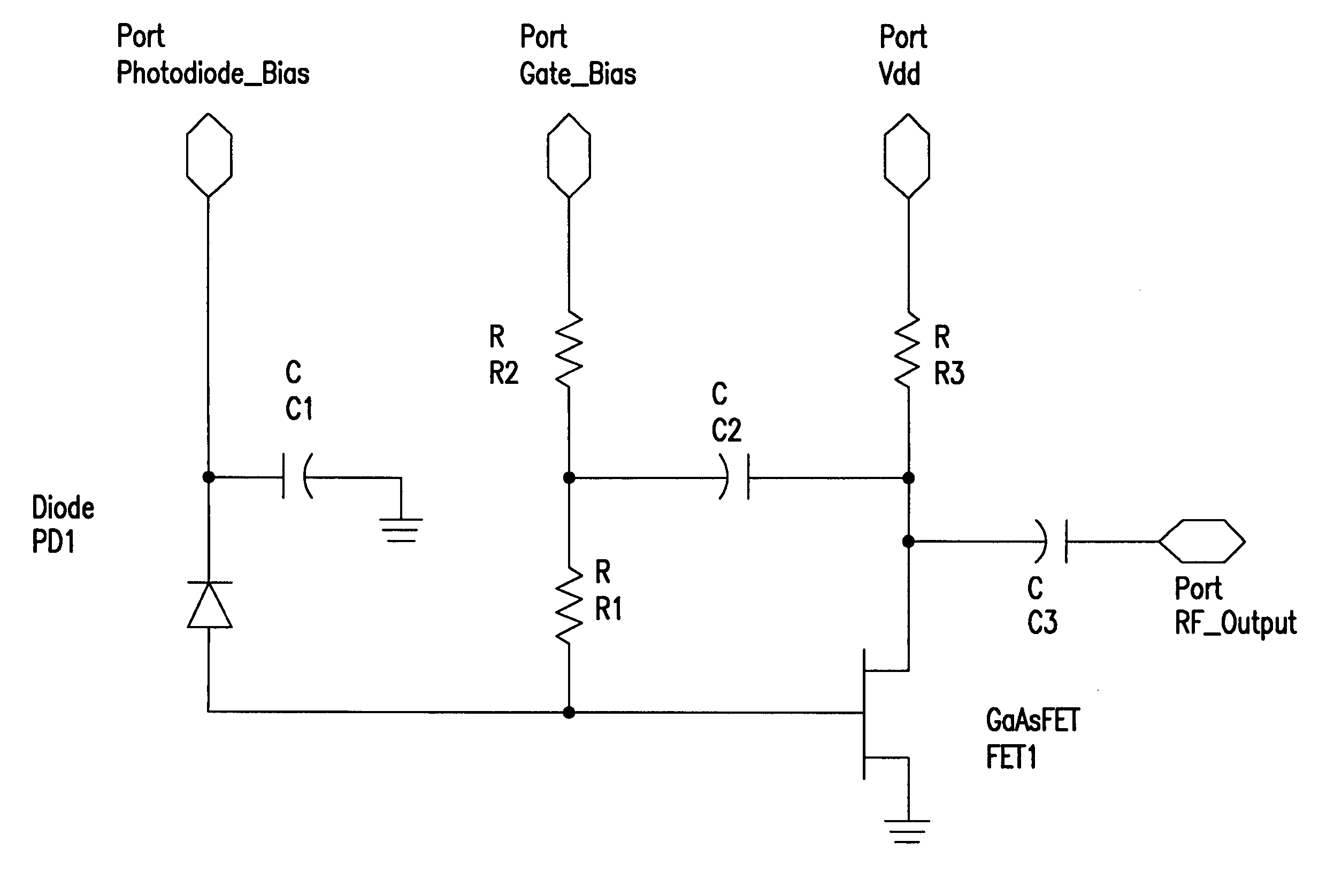
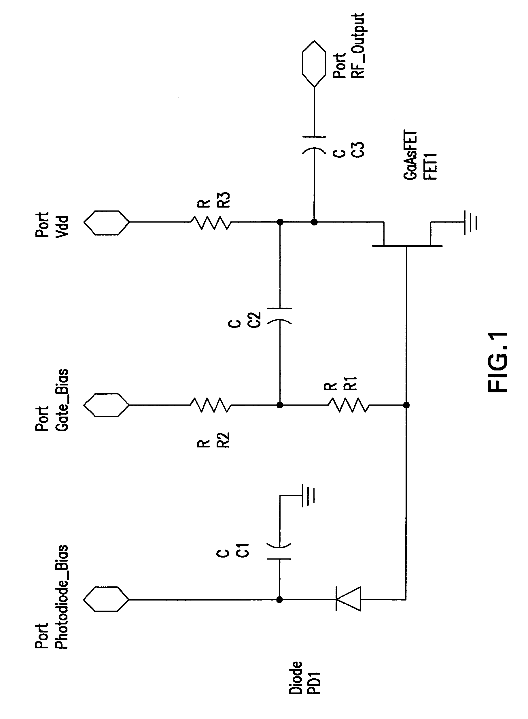
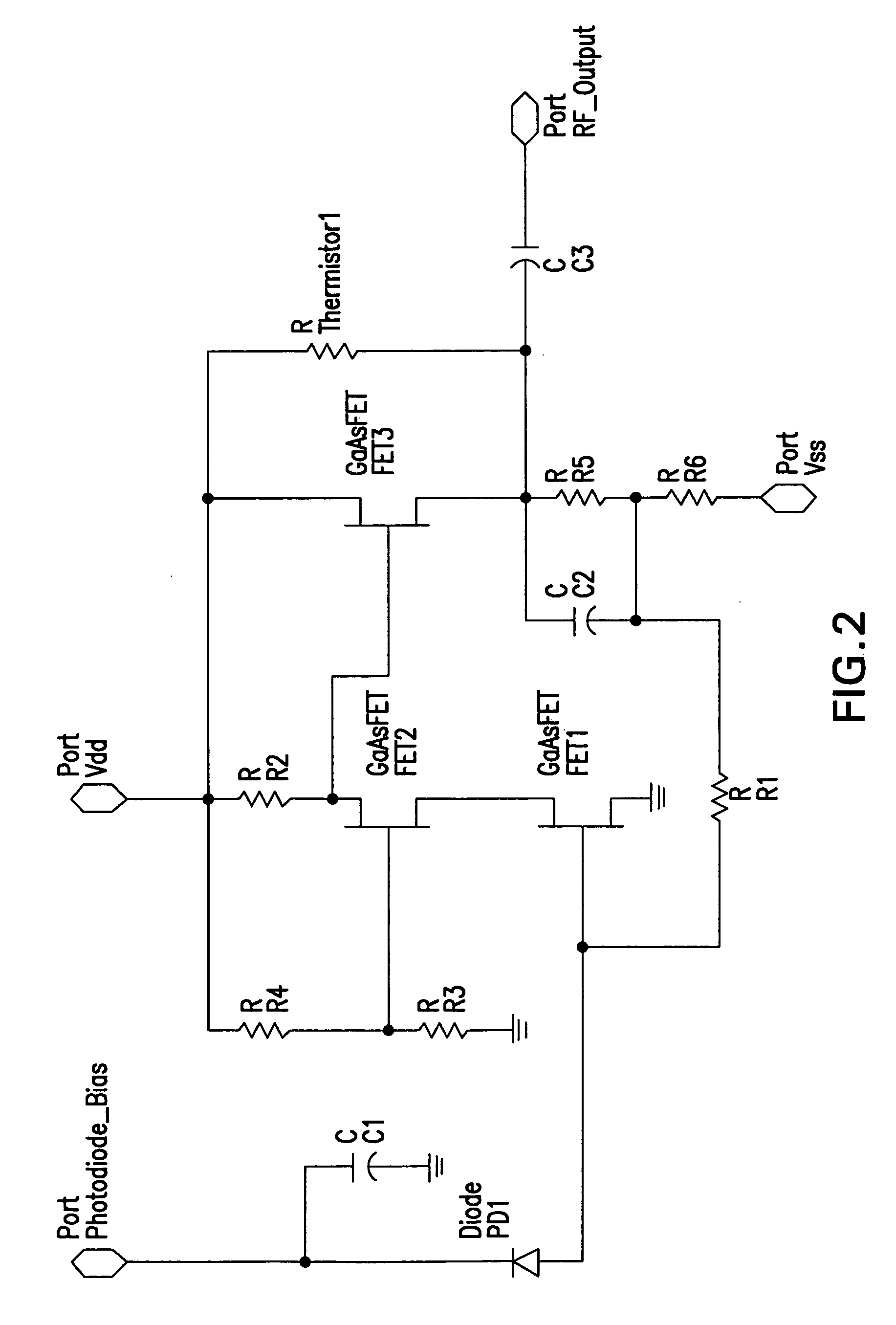
[0031] For new Fiber-to-the-Home (FTTH) applications that include an analog optical CATV receiver at each customer premise, there is a strong desire on the part of network interface hardware manufacturers and service providers (such as telephone or cable operating companies) to reduce power dissipation and to lower hardware cost. To this end, the present invention provides a new design for a single-ended analog TIA with power dissipation low enough to all...


PUM


Abstract

An optical receiver for use in an optical communications system in which an analog signal is transmitted over an optical fiber including a housing with a photodetector coupled to the external optical fiber for receiving an optical communications signal; and a transimpedance amplifier coupled to the electrical output of the photodetector and having a bias current in a second stage set to a predetermined value that minimizes the distortion in the output signal created in a first amplification stage by a cancellation effect.

Description

BACKGROUND OF THE INVENTION [0001] 1. Field of the Invention [0002] The invention relates to optical receivers, and in particular to transimpedence amplifiers that have a non-linear operating characteristic and provide an interface between a photodiode that receives an optical signal from an optical fiber, such as used in fiber optical communications links, and electronic network terminal units. [0003] 2. Description of the Related Art [0004] A variety of optical communications systems are known in the art which include an optical transmit portion that converts an electrical signal into a modulated light beam that is coupled to an optical fiber, and a receive portion that receives an optical signal from an optical fiber and converts it into an electrical signal. Traditionally, optical receive sections include an optical assembly to focus or direct the light from the optical fiber onto a photodetector, which in turn, is connected to an amplifier / limiter circuit on a circuit board. Th...

Claims


Application Information

Patent Timeline
IPC IPC(8): H04B10/06H04B10/43
CPCH03F1/223H03F1/226H03F1/301H03F3/505H03F1/3211H03F3/082H03F3/087H03F1/3205
Inventor KASPER, BRYON LYNNPERAL, EVA MARIE
Owner EMCORE INC
Learn More