Wavelet transform of a plethysmographic signal

a wavelet transform and plethysmographic technology, applied in the field of photoplethysmography, can solve the problems of inadequacies in the extraction of desired patient physiological conditions, affecting the accuracy of the signal, so as to improve the identification of repeating events

Active Publication Date: 2007-01-04
GENERAL ELECTRIC CO
View PDF8 Cites 60 Cited by
  • Summary
  • Abstract
  • Description
  • Claims
  • Application Information

AI Technical Summary

Benefits of technology

[0019] According to another aspect of the present invention, a utility is provided where a dual wavelet transform is performed on a time-based pleth signal in order to identify and remove nonstationary events from the time-based signal. In this regard, the first wavelet transform is performed on a first portion of the time-based signal. This first wavelet transform has a narrow time window and a wide frequency band to allow for identifying peaks within the time-based signal. A second wavelet transform may then b

Problems solved by technology

However, motion artifacts can easily swamp the desired information (i.e., the signal of interest) included in the plethysmographic signals when the patient is moving around and/or performing muscular contractions.
Other sources of artifact or ‘noise’ that can occlude the signal of interest in a plethysmographic signal include power line noise, electrical noise from other medical equipment and light contamination.
Some artifacts can severely impair the signals, whereas other types can be filtered out or do not significantly effect the desired information included in the plethysmographic signals.
Furthermore, depending upon the severity and type of artifacts present in the plethysmographic signals, some techniques for extracting the desired patient physiological conditions may not be appropriate and alternative techniques may need to be employed.
However, in high motion conditions, the noise signal may overwhelm the periodic signal of the heart such that the fundamental cannot be effectively determined by simple Fourier analysis.
Further, it is often the case that the frequency spectr

Method used


Image

  • Wavelet transform of a plethysmographic signal
  • Wavelet transform of a plethysmographic signal
  • Wavelet transform of a plethysmographic signal

Examples


Embodiment Construction

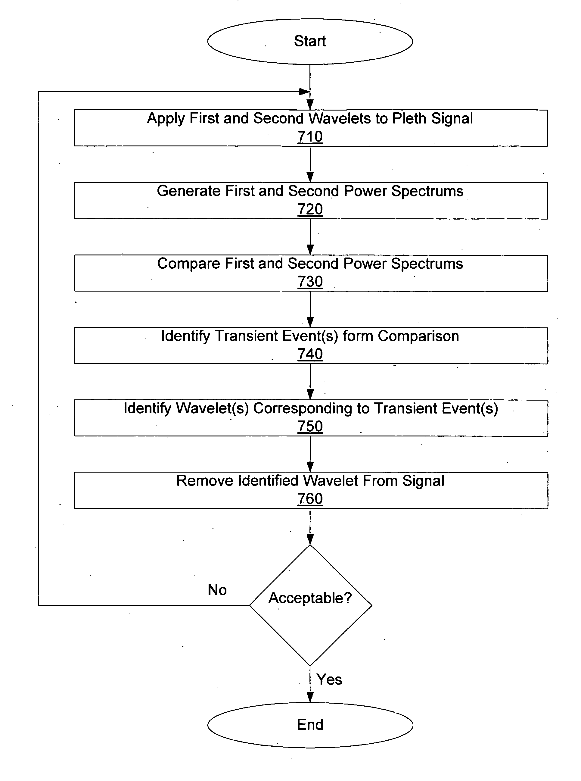
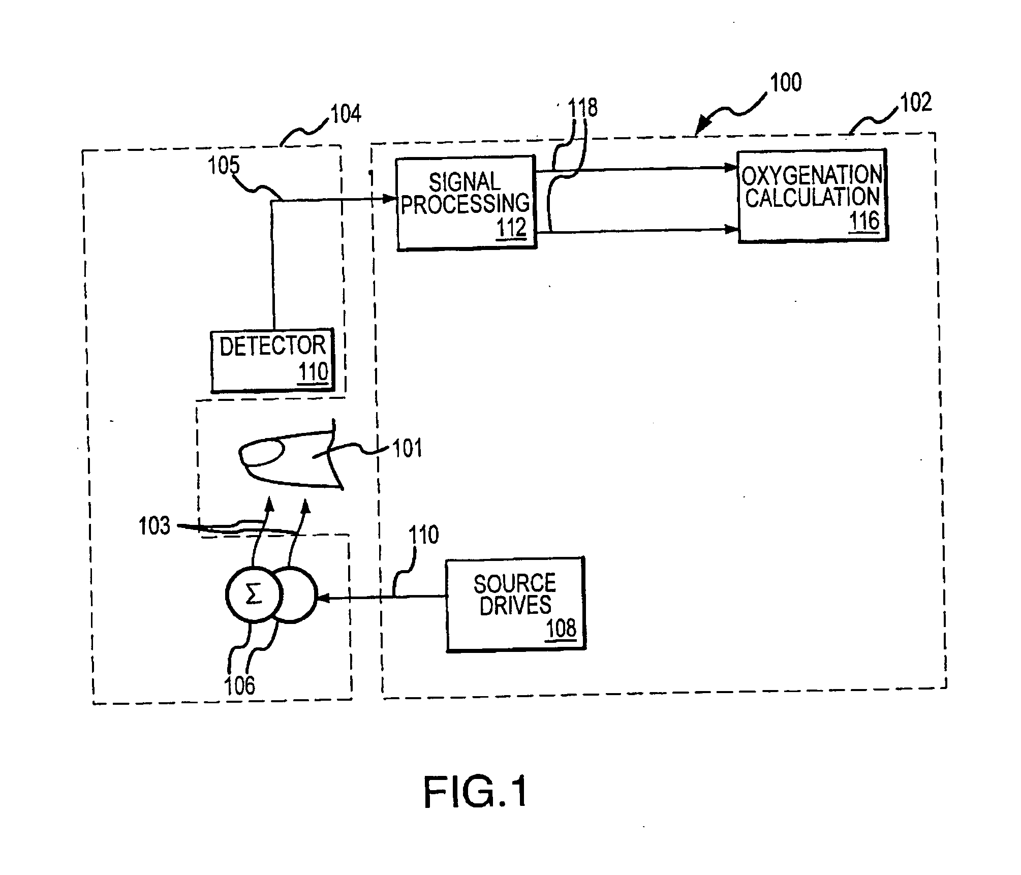
[0030] The present invention relates generally to obtaining physiological parameter information for a patient based on an analysis of a pleth signal. More specifically, the present invention is related to distinguishing effects associated with artifact from a signal portion of interest in a raw pleth signal such that the effects associated with motion may be attenuated or removed prior to use of the pleth for obtaining physiological parameter information. In the following discussion, the invention is described in the context of an implementation utilizing components of a conventional two-channel pulse oximeter. However, it will be appreciated that various aspects of the invention are not limited to such a pulse oximeter or other multi-channel signal implementation and the invention may be embodied in a dedicated single or multi-channel photoplethysmography instrument. Accordingly, the following discussion should be understood as exemplifying the invention and not by way of limitatio...


PUM


Abstract

A photoplethysmographic system and method is provided for filtering a photoplethysmographic (pleth) signal to reduce the effects of noise in the signal. The system and method utilize a combination of frequency, time and/or magnitude information, to identify and separate transient signal components within a pleth signal from repeating signal components within the pleth signal. Typically, signal components of interest repeat over a period that corresponds with a patient's heartbeat. Such periodically repeating signals may be identified as stationary signals/objects within a frequency and time-based analysis. In contrast, motion artifacts or other sources of noise are often isolated (i.e., non-repeating) transient events and may be identified as non-stationary objects in a frequency and time-based analysis. Data associated with identified transient events may be filtered from or otherwise removed from a given signal. In this regard, a pleth signal may be cleansed prior to its use for, e.g., blood analyte determinations.

Description

FIELD OF THE INVENTION [0001] The present invention relates generally to photoplethysmography and, in particular, to filtering a photoplethysmographic signal so as to reduce the effects of noise in the signal. BACKGROUND OF THE INVENTION [0002] Pulse oximeters determine an oxygen saturation level of a patient's blood, or related analyte values, based on transmission / absorption characteristics of light transmitted through or reflected from a patient's tissue. In particular, pulse oximeters generally include a probe for attaching to a patient's appendage such as a finger, earlobe or nasal septum. The probe is used to transmit pulsed optical signals of at least two wavelengths, typically red and infrared, through the patient's appendage. The transmitted signals are received by a detector that provides an analog electrical output signal representative of the received optical signals. By processing the electrical signal and analyzing signal values for each of the wavelengths at different...

Claims


Application Information

Patent Timeline
IPC IPC(8): A61B5/00
CPCA61B5/14551A61B5/726A61B5/7207A61B5/7203
Inventor NORRIS, MARK A.
Owner GENERAL ELECTRIC CO
Why Eureka
Try Eureka