Lateral and longitudinal velocity determination for an automotive vehicle

a technology for determining the lateral and longitudinal velocity of an automotive vehicle, which is applied in the direction of pedestrian/occupant safety arrangements, cycle equipment, instruments, etc., can solve the problems of inaccurate measurement of longitudinal vehicle velocity by wheel speed, inaccurate estimation accuracy, and inability to optimize vehicle performance for ride, so as to accurately estimate the vehicle velocities

Inactive Publication Date: 2007-01-04
FORD GLOBAL TECH LLC
View PDF5 Cites 50 Cited by
  • Summary
  • Abstract
  • Description
  • Claims
  • Application Information

AI Technical Summary

Benefits of technology

[0007] It is the primary objective of the present invention to provide a methodology of estimating the vehicle longitudinal velocity and lateral velocity of the vehicle. The proposed methodology may use the following sensors: (i) a low-cost strapdown IMU sensor cluster, (ii) a steering wheel angle sensor, (iii) and wheel speed sensors. The method utilizes the kinematic relationship among sensor signals, a bicycle model, and the nonholonomic constraints for a vehicle moving on a surface. The vehicle velocity estimates are obtained via a fusion of the data from all the sensors.
[0008] It is another objective of the present invention to provide a technique of qualifying different sensor signals so that they may be fused to accurately estimate the vehicle velocities. A number of criteria are proposed for identifying cases that are not suitable for using one sensor signal but suitable for using others. As a result, the proposed sensing algorithm is robust to sensor bias and noise, vehicle maneuvers, vehicle parameter variation, road disturbances and the friction coefficient between the tires and the road.
[0009] It is yet another objective of the present invention to optimize the vehicle performance for ride, safety and fuel economy by providing an accurate estimate of the vehicle velocity. Even in future vehicle models equipped with standard GPS devices, the proposed methodology is able to help achieve desired performance when sky-obstruction / GPS faults occur.

Problems solved by technology

Also in these situations, the longitudinal vehicle velocity cannot be accurately measured by wheel speed because of excessive wheel slip.
Although it is possible to measure vehicle velocities directly by using dedicated measuring devices such as optical sensor and GPS, there are practical issues such as cost, accuracy and reliability that prevent the use of such devices on production vehicles.
The estimation accuracy, however, can be very crude for a lot of maneuvers / road conditions, which in turn severely limits the control performance.
The reduction in size and cost, especially cost, however, has also led to a drop in accuracy of the inertial unit as a whole.
These errors are added up via mathematical integration, and may lead to large drifts in the attitude and velocity estimates, unless external absolute sensors are used to constantly bound the errors.
While fairly good estimation accuracy may be attained in open sky environment using this approach, the performance deteriorates when the satellite signals bounce off of reflective surfaces such as tall buildings and other structures in the “urban canyon.” In the worst case, when fewer than three or four satellites can be “seen” (i.e., driving through a tunnel), the GPS provides no information to bound the errors associated with high frequency inertia sensors.
Another disadvantage is that GPS devices are not at all common and / or cost effective on current production vehicles.

Method used


Image

  • Lateral and longitudinal velocity determination for an automotive vehicle
  • Lateral and longitudinal velocity determination for an automotive vehicle
  • Lateral and longitudinal velocity determination for an automotive vehicle

Examples


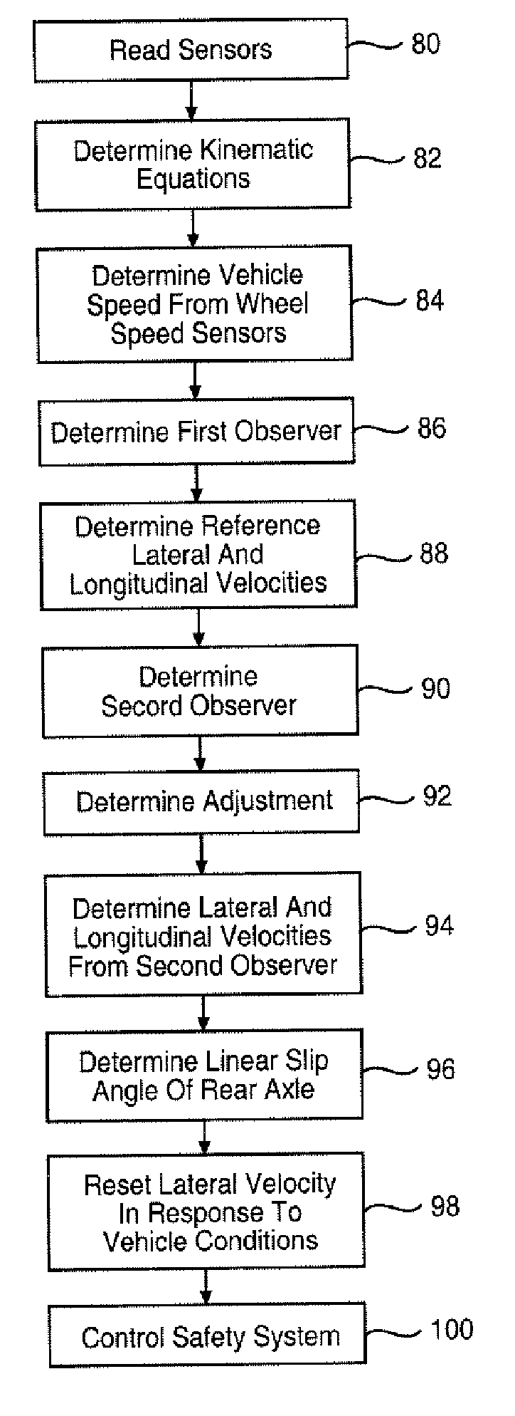
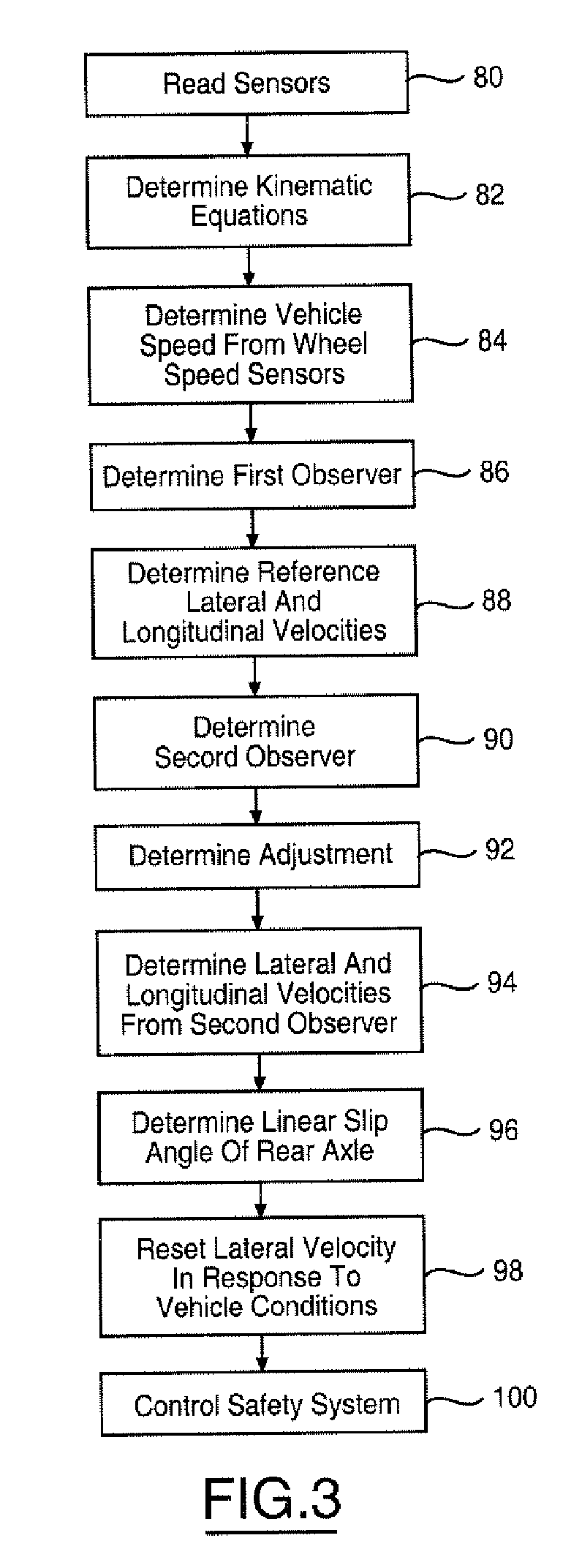
Embodiment Construction

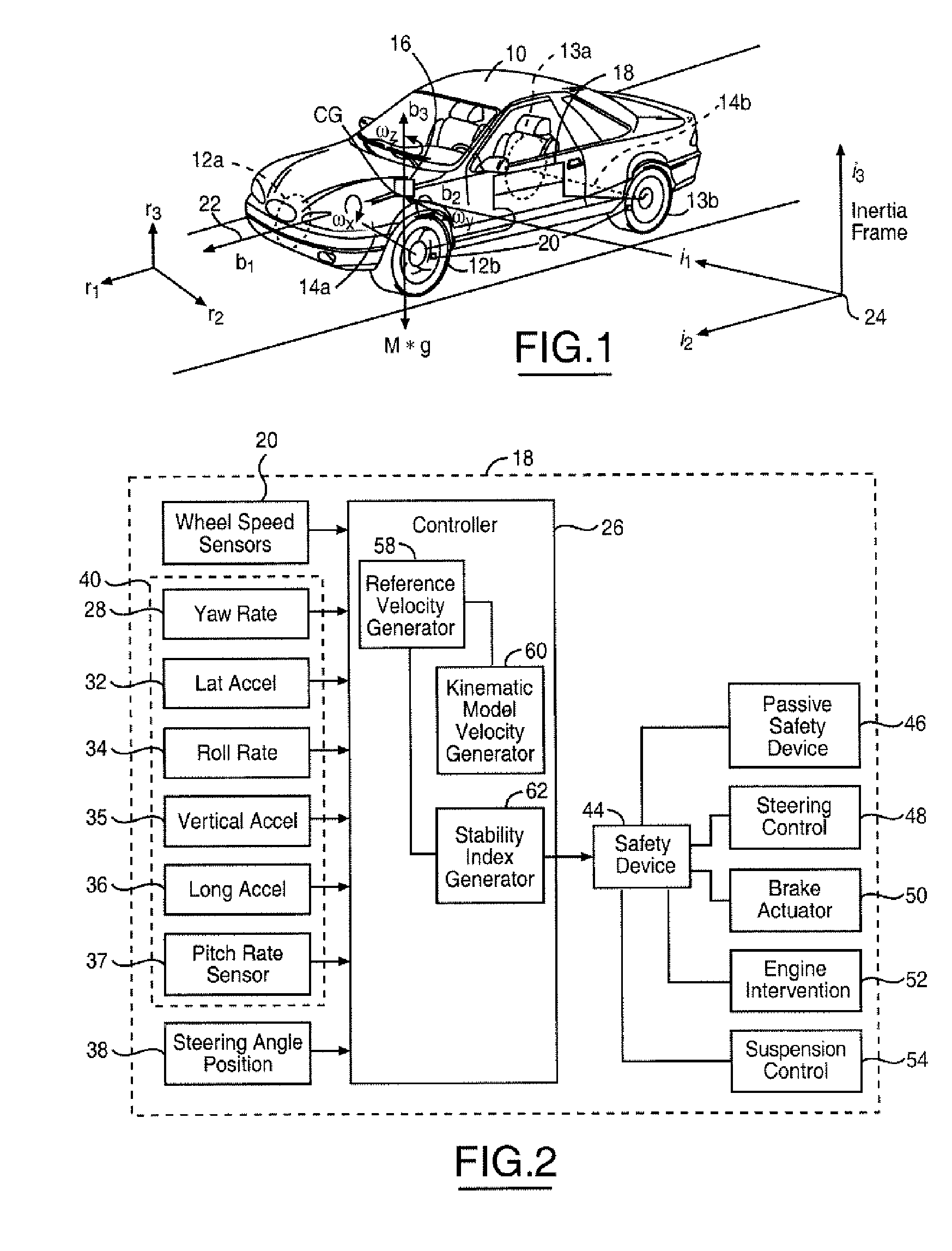
[0014] In the following figures the same reference numerals will be used to identify the same components.

[0015] The present invention may be used in conjunction with a dynamic control system of a vehicle such as a rollover control system or a yaw stability control system. However, the present invention may also be used with a deployment device such as an airbag or roll bar. The present invention will be discussed below in terms of preferred embodiments relating to an automotive vehicle moving in a three-dimensional road terrain.

[0016] Referring to FIG. 1, an automotive vehicle 10 with a safety system of the present invention is illustrated with the various forces and moments thereon during a rollover condition, spinning out condition, and plowing condition. Vehicle 10 has front right and front left tires 12a and 12b and rear right tires 13a and left rear tires 13b, respectively. The vehicle 10 may also have a number of different types of front steering systems 14a and rear steerin...


PUM


Abstract

A system (18) for controlling a safety system (44) of an automotive vehicle (10) includes a longitudinal acceleration sensor (36), a vehicle speed sensor (20), a lateral acceleration sensor (32), a yaw rate sensor, and a controller (26). The controller (26) determines a stability index and provides a first observer that determines a reference longitudinal velocity in response to the longitudinal acceleration signal, the yaw rate signal, a pitch attitude and vehicle speed from wheel speed sensors. The controller (26) determines a reference lateral velocity in response to the lateral acceleration signal, the yaw rate signal, a roll attitude, a pitch attitude and vehicle speed from the wheel speed sensors. The controller provides a second observer that determines a second longitudinal velocity in response to the longitudinal acceleration signal, the yaw rate signal, a lateral velocity, the pitch attitude and a first adjustment based on the longitudinal reference velocity. The controller determines a second lateral velocity in response to the lateral acceleration signal, the yaw rate signal, a roll attitude, a pitch attitude and a second adjustment based on the lateral reference velocity. The controller determines an output lateral velocity and an output longitudinal velocity in response to the first observer, second observer and the stability index. The controller controls the safety system in response to the output lateral velocity and the output longitudinal velocity.

Description

TECHNICAL FIELD [0001] The present invention relates generally to a control apparatus for controlling a system of an automotive vehicle in response to sensed dynamic behavior, and more specifically, to a method and apparatus for controlling the system of the vehicle by determining the lateral and longitudinal velocity of the vehicle. BACKGROUND [0002] In recent years, various vehicle yaw stability control systems that prevent vehicles from spinning out and drifting using differential braking have been developed. Lateral velocity (or side slip angle) is one of the most important vehicle dynamic variables for these systems and is also crucial for many other chassis control functions. In critical dynamic situations, lateral velocity is necessary to detect and then control an unstable vehicle which may have normal yaw rates. Also in these situations, the longitudinal vehicle velocity cannot be accurately measured by wheel speed because of excessive wheel slip. Hence a successful vehicle...

Claims


Application Information

Patent Timeline
Patent Type & Authority Applications(United States)
IPC IPC(8): B60G17/016G06F17/00B60W30/02B60W40/10
CPCB60R21/0132B60R2021/01327B60T8/172B60W40/10B60W30/02B60W30/045B60T2250/04B60T8/1755
Inventor XU, LITSENG, HONGTEI ERICMEYERS, JOSEPH C.
Owner FORD GLOBAL TECH LLC
Why Eureka
Try Eureka