The longer an error takes to be detected and corrected, the more time consuming and costly a redesign becomes.
Moreover, the longer an error takes to be detected and corrected, the longer it takes for the product to reach the marketplace.
A challenge of
software-based cycle simulation is that the process can be very slow.
Simulating complex designs with large gate counts exacerbates this challenge.
In an era of gigahertz-class computer systems, simulating a large complex design can mean that months of simulation are required to simulate just one second of actual hardware time.
As a result, errors which occur deep in the design which are visible only after thousands or millions of cycles of operation may go undetected.
Failing to detect these errors often results in hardware being produced, at the cost of millions of dollars, that has errors.
Another challenge of slow simulation speeds is that it hinders
software development for the
software being developed to run on the hardware that is being designed.
Slow simulation of hardware also hinders the development of related software.
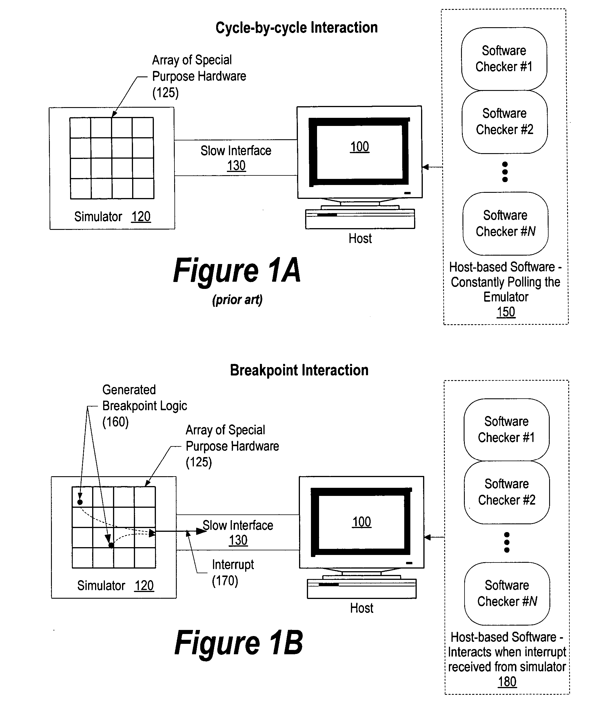
While these hardware simulators are often hundreds or thousands of times faster than using software-based cycle simulation, maximum performance can only be achieved when communication between the
hardware simulator and the host across a service interface is minimized.
A challenge of minimizing this communication is that cycle-by-cycle state changes are no longer visible to either external function checkers or to the software developer.
As a result of the restricted debugging information available using hardware simulation, hardware simulation has traditionally been used in a limited fashion and predisposed to programs that are self-checking.
Unfortunately, there are significant challenges using in-circuit checks.
First, the in-circuit checks are limited in functionality and complexity as compared to software checkers that are written in a higher level language, such as C or C++.
Second, in-circuit checks are expensive in terms of time and resources to prepare as compared to using software checkers.
Finally, in-circuit checks require an intimate working knowledge of the hardware design—this is a skill that is not always available in
verification teams whose staff may be more software oriented.
While simulators allow simulation of millions of
clock cycles necessary to run real software, the communications
bottleneck prevents cycle-by-cycle
visibility of key hardware resources without dramatically impacting the speed of the simulation.
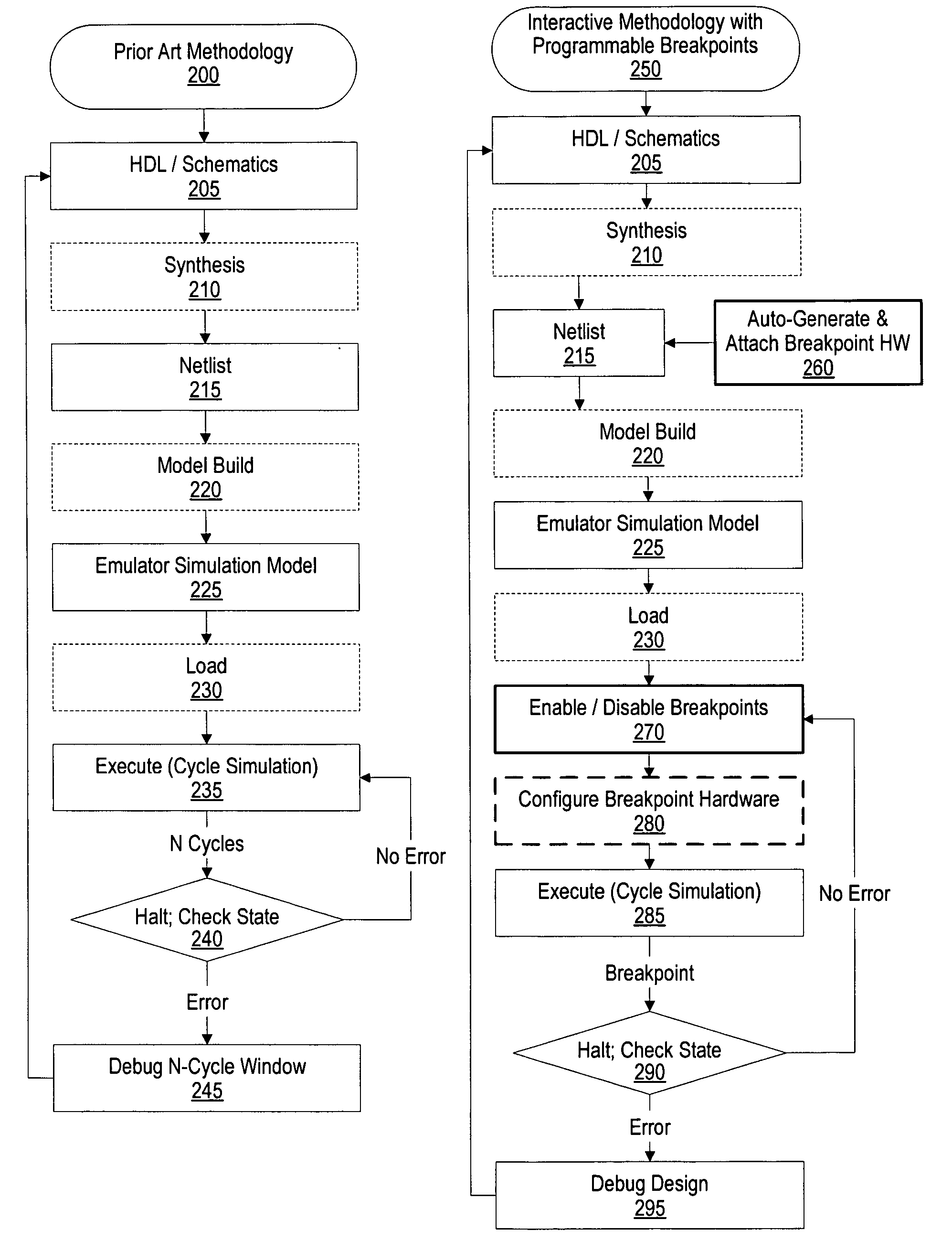
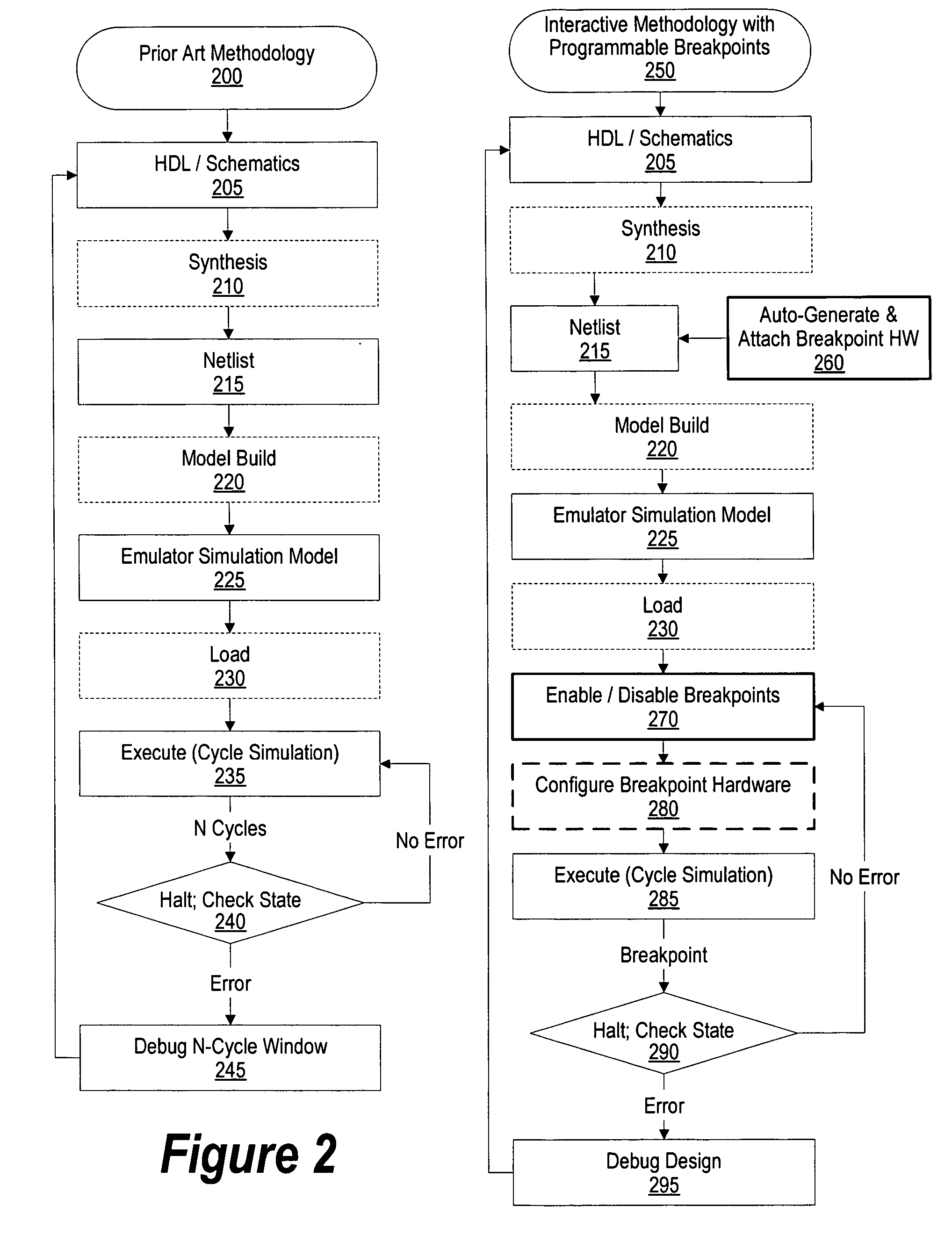
A challenge to using hardware breakpoints is that they are defined beforehand and are time consuming to change in order to break on a different event or
signal.
Performing these steps is a lengthy process, often taking several hours to complete.
Finally, an additional challenge to using breakpoints is that they also require hardware expertise in order to write.

