
Transmitting and receiving circuitry for an ultrasonic flowmeter, and method for operating such transmitting and receiving circuitry

a technology ultrasonic flowmeters, applied in the direction of volume/mass flow, dynamic fluid flow effect, measurement devices, etc., to achieve the effect of improving the performance of transmitting and receiving circuits, maximizing transmission performance, and improving signal-to-noise ratio

Active Publication Date: 2007-01-11
KRONE GMBH
View PDF3 Cites 3 Cited by
  • Summary
  • Abstract
  • Description
  • Claims
  • Application Information

AI Technical Summary

Benefits of technology

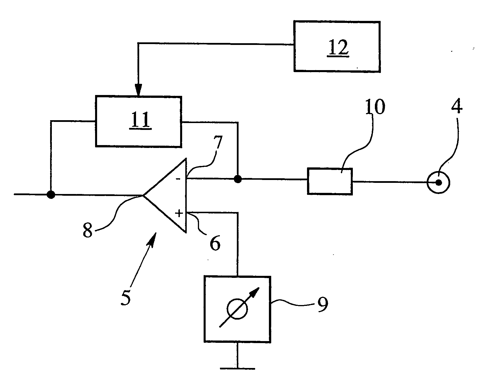
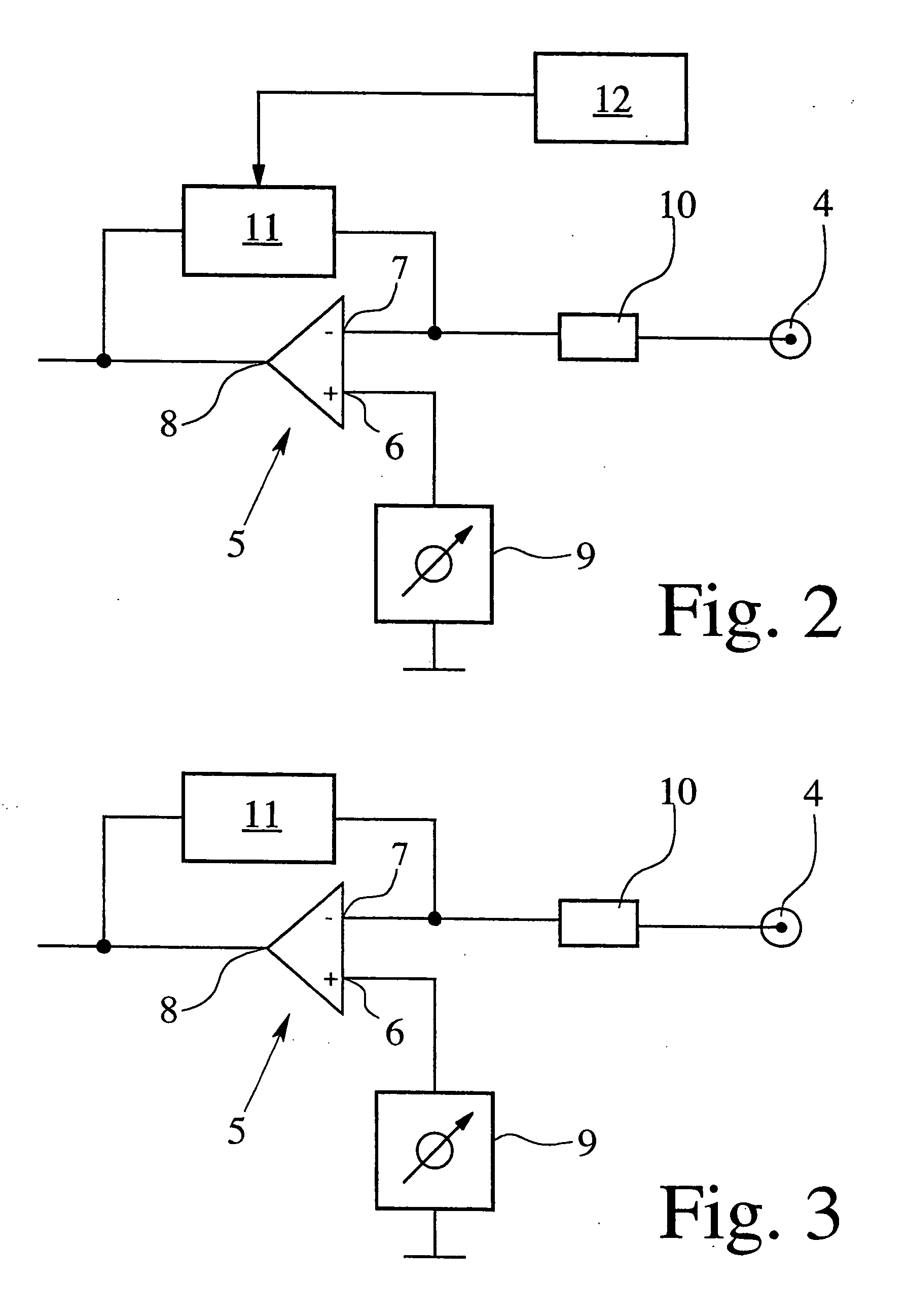
[0008] In the development of this invention, it was discovered that the performance of the transmitting and receiving circuitry and especially the signal-to-noise ratio can be significantly improved by adapting the impedance of the feedback element to the different operating modes of the transmitting and receiving circuitry. In the transmitting mode in which the signal generator generates voltage signals and sends these to the ultrasound transducer that is connected to the ultrasound transducer port, the impedance of the feedback element is advantageously reduced to a relatively low value to achieve optimal transmission performance. In the receiving mode, on the other hand, the impedance of the feedback element is advantageously increased to a higher value since an augmentation of the impedance of the feedback element is accompanied by a correspondingly greater gain factor.

Problems solved by technology

However, this mode is not intended for measuring operations but rather for testing purposes in the course of which it is possible, for instance, to determine the propagation time in an ultrasonic waveguide installed in the ultrasonic flowmeter, to ascertain whether all transducers and cables are properly connected, to check the performance parameters of the transducers or to verify that a signal reflected by the medium flowing through the measuring tube is received.

Method used


Image

  • Transmitting and receiving circuitry for an ultrasonic flowmeter, and method for operating such transmitting and receiving circuitry
  • Transmitting and receiving circuitry for an ultrasonic flowmeter, and method for operating such transmitting and receiving circuitry
  • Transmitting and receiving circuitry for an ultrasonic flowmeter, and method for operating such transmitting and receiving circuitry

Examples


Embodiment Construction

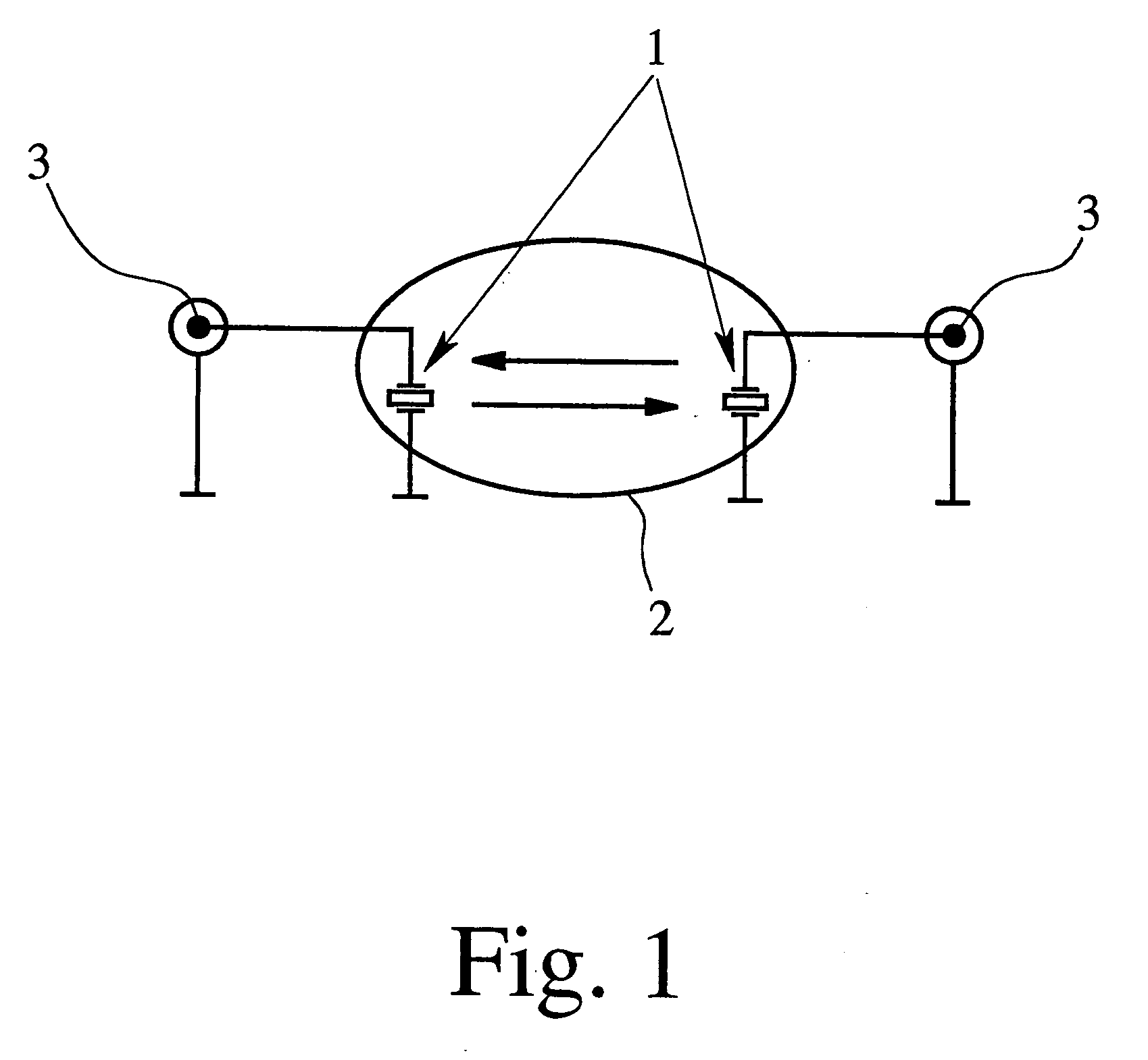
[0024]FIG. 1 shows in skeletonized schematic fashion the conceptual principle of an ultrasonic flowmeter. It includes two ultrasound transducers 1, positioned in a mutually off-set arrangement in a measuring tube 2 through which flows a fluid medium. The illustration in FIG. 1 corresponds to a cross section through a cylindrical measuring tube 2, with the sectional plane defined by the two ultrasound transducers 1 and extending at a 90° angle relative to the longitudinal axis of the measuring tube 2 and thus to the flow direction of the medium traveling through the measuring tube 2.

[0025] The two ultrasound transducers 1 are each provided with a connecting port 3 for connection to a transmitting and receiving circuitry system. The following describes transmitting and receiving circuitry systems according to preferred embodiments of the invention that can be connected to these ports 3.

[0026]FIG. 2 shows a transmitting and receiving circuitry design for an ultrasonic flowmeter accor...


PUM


Abstract

A transmitting and receiving circuitry system for an ultrasonic flowmeter includes an ultrasound transducer interface for connection to an ultrasound transducer of the ultrasonic flowmeter, an amplifier with a first input and a second input, as well as a signal generator for activating the ultrasound transducer, with the first input of the amplifier connecting to the signal generator while the second input of the amplifier connects both to the ultrasound transducer interface and, via a feedback element, to the output of the amplifier. The impedance of the feedback element can be varied, permitting an adaptation of the transmitting and receiving circuitry to the operating mode of the ultrasonic flowmeter, in particular an adaptation to a transmitting or receiving mode, whereby an overall improvement of the signal-to-noise ratio is attainable. A method for operating such a system is also disclosed.

Description

BACKGROUND OF THE INVENTION [0001] This invention relates to a transmitting and receiving circuitry system for an ultrasonic flowmeter, with an ultrasound transducer interface for connection to an ultrasound transducer of the ultrasonic flowmeter, an amplifier with a first input and a second input, as well as a signal generator for activating the ultrasound transducer, with the first input of the amplifier connecting to the signal generator while the second input of the amplifier is connected to both the ultrasound transducer interface and, via a feedback element, to the output of the amplifier. The invention further relates to an ultrasonic flowmeter employing such transmitting and receiving circuitry and to a method for operating such transmitting and receiving circuitry. [0002] In the operation of ultrasonic flowmeters, ultrasound waves are used for measuring the speed and flow rate of a fluid medium traveling through a measuring tube. The parameters that can be derived from the ...

Claims


Application Information

Patent Timeline
Patent Type & Authority Applications(United States)
IPC IPC(8): G01F1/66
CPCG01F1/667
Inventor HUIJZER, ARIE
Owner KRONE GMBH
Learn More