
Apparatus and method for storing and dispensing material, especially in micro quantities and in combination with limited starting amounts

Inactive Publication Date: 2007-01-11
FREESLATE
View PDF25 Cites 46 Cited by
  • Summary
  • Abstract
  • Description
  • Claims
  • Application Information

AI Technical Summary

Benefits of technology

[0023] The invention comprises a dispensing device which has, compared to the devices known from prior art, a simple setup suitable to be made of metal or injection moulded plastic, depending on the field of application. The device is made that it is easy to be filed and to be emptied without the need of extensive cleaning. Therefore it is relevant that only a limited amount of parts are in direct contact with the material to be dispensed whereby these parts are easy to clean and to maintain. Compared to the prior art, one advantage of the invention consists in that the device offers the possibility for miniaturisation which is one condition for handling small amounts of material. The device is further suitable to be used with materials in powdery and / or granular form having different physical characteristics such as e.g. particle size, shape and form, density, humidity. The device further provides a high repeating accuracy such that it is e.g. possible to dispense thirty portions of 1 mg or sixty portions of 0.5 mg or a fraction of it, with a high accuracy by a single dispenser. Therefore the dispenser according to the present invention is especially suitable to be used in laboratories e.g. of the pharmaceutical and biotechnological industry and particularly for small-scale scientific research. The device avoids any risk of cross-contamination since the openings can be sufficiently sealed if necessary.
[0024] To provide a high accuracy the device preferably comprises or is interconnectable to at least one scaling means to directly or indirectly measure the amount of material dispensed. For direct measuring the scaling device is interconnected to the dispensing device itself, measuring the amount of material leaving the dispensing device. Alternatively or in addition the scaling device, for indirect measuring, is interconnected to the container determined to receive the dispensed material.
[0025] The dispensing device in general comprises at least one compartment to receive a material to be distributed, a gate valve, preferable a gate valve with variable opening, an agitator, and a conveyor. The gate valve, the agitator and the conveyor are driven by at least one drive mechanism which forms part of the dispensing device or to which the dispensing device may be interconnected by interfaces. In a preferred embodiment the agitator and the conveyor are incorporated in a single device. Depending on the field of application the dispensing device further comprises a storing means to hold information temporarily or permanent e.g. about the material, amount and condition of the material contained in the dispensing device. If appropriate the dispensing device may further comprise at least one sensor to retrieve information about the condition, such as humidity, temperature or electric conductivity, of the material contained in the dispenser.
[0026] A control unit which may form part of the dispensing device or to which the dispensing device may be interconnected controls the position and opening of the gate valve, the agitator and / or the conveyor. The control unit is, if present, further interconnected to the at least one scaling means to control or double check the amount dispensed from the dispensing device. The control unit may further comprise means to read out and store information from the storing means.
[0027] In a preferred embodiment the dispensing device is designed as an exchangeable unit having a first standardized interface suitable to be interconnected with an appropriate second standardized interface of a controller. The controller is thereby suitable to receive different dispensing devices, e.g. of different size or containing different materials. When not interconnected to the controller the different dispensing devices are preferably stored in a storing unit tightly sealed. Exchanging of the dispensing devices takes preferably place by an exchanging device which is suitable to exchange the dispensing devices automatically.
[0028] Due to the large flexibility and the setup it is possible to provide an adapter means by which the dispensing device according to the present invention may be interconnected to existing control devices as known from the prior art. The adapter means is foreseen to transfer control variables and if appropriate feedback information between the dispensing device and the control device for adjusting the opening of the gate valve.

Problems solved by technology

One disadvantage consists in that the device is not suitable for small amounts of material.
With these devices the minimum amount possible to be dispensed is given by the smallest standardized container available and a fine graduation is therefore difficult to achieve.
A further disadvantage is the logistic effort necessary to produce, handle and store the different containers.
Still a further disadvantage consists in that the remains of the containers have to be disposed or separated form the mixtures.
The dispensers known from prior art are not suitable for automatic dispensing of small starting amounts in the range of that needs to be dispensed into typically used vessels and receptacles, such as plates, vials, bottles, capsules, etc., in very low quantities, like 1 mg or less.
One reason for this problem consists in that the known devices are to large or have to many parts involved such that, due to the large surface of the parts involved, small quantities of powder may not be handled.
Also, the waste of the powder, caused by the known devices, is considerable.
Another draw back is that the devices known from prior art in general consist of a large number of parts which are difficult to manufacture, assemble, maintain and clean.
A further draw back is that the devices known from prior art have to be adjusted according to the physical characteristics of the material to be dispensed or cannot be used for dispensing of cohesive powders.
In addition, the known devices do loose powder during operation because they are not sufficiently sealed.
Uncontrolled loss of powder may cause serious problems and contamination.

Method used


Image

  • Apparatus and method for storing and dispensing material, especially in micro quantities and in combination with limited starting amounts
  • Apparatus and method for storing and dispensing material, especially in micro quantities and in combination with limited starting amounts
  • Apparatus and method for storing and dispensing material, especially in micro quantities and in combination with limited starting amounts

Examples


Embodiment Construction

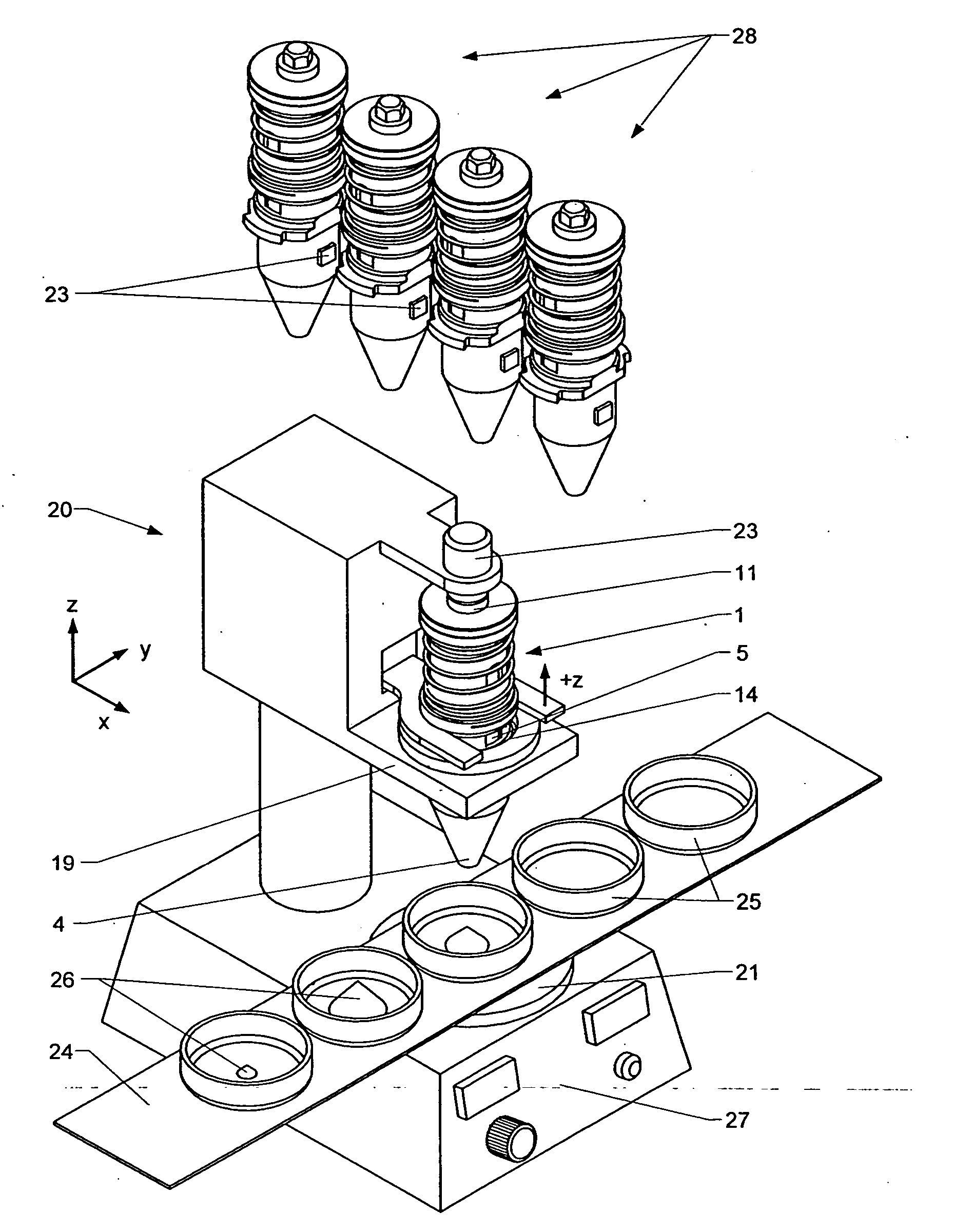
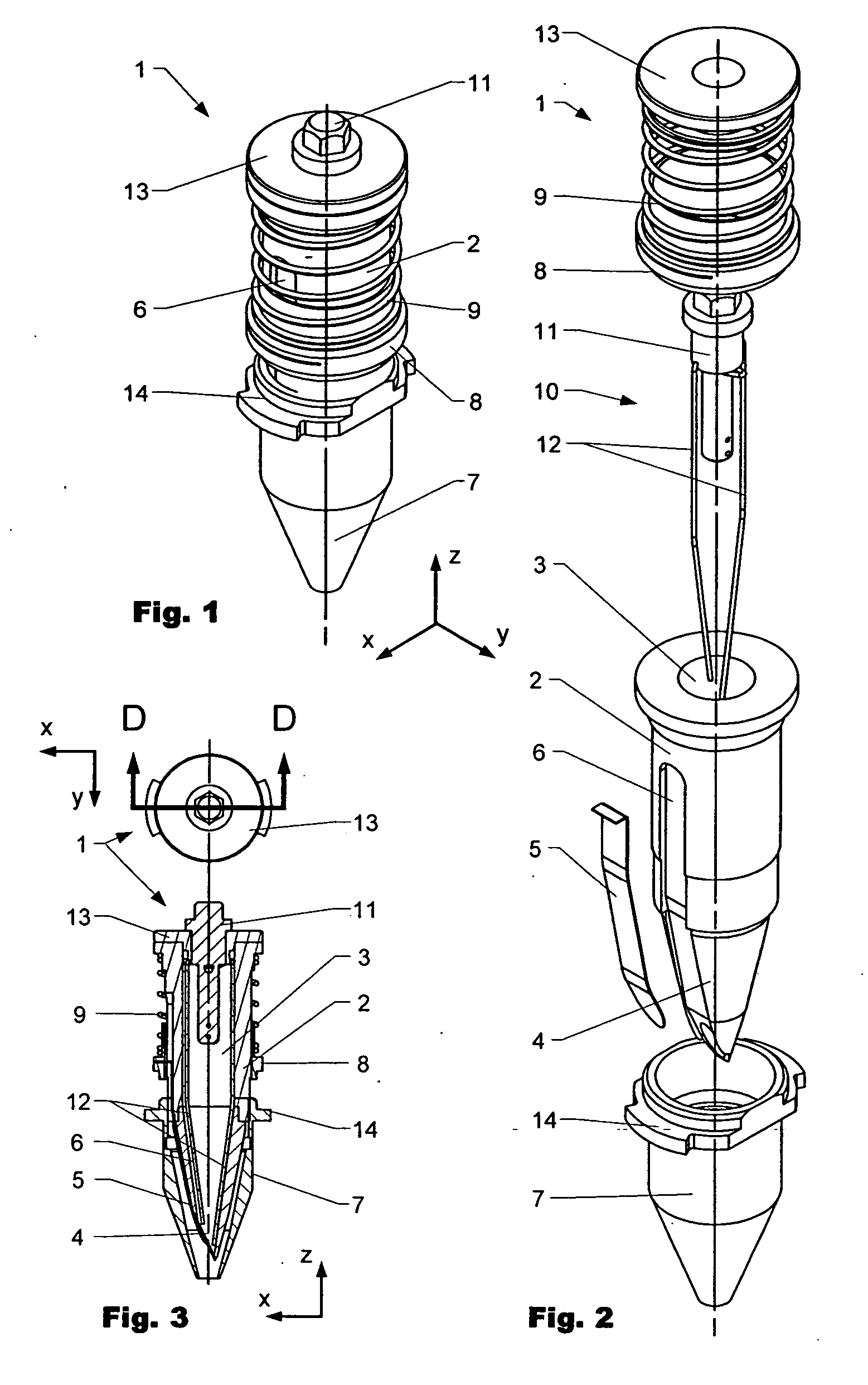
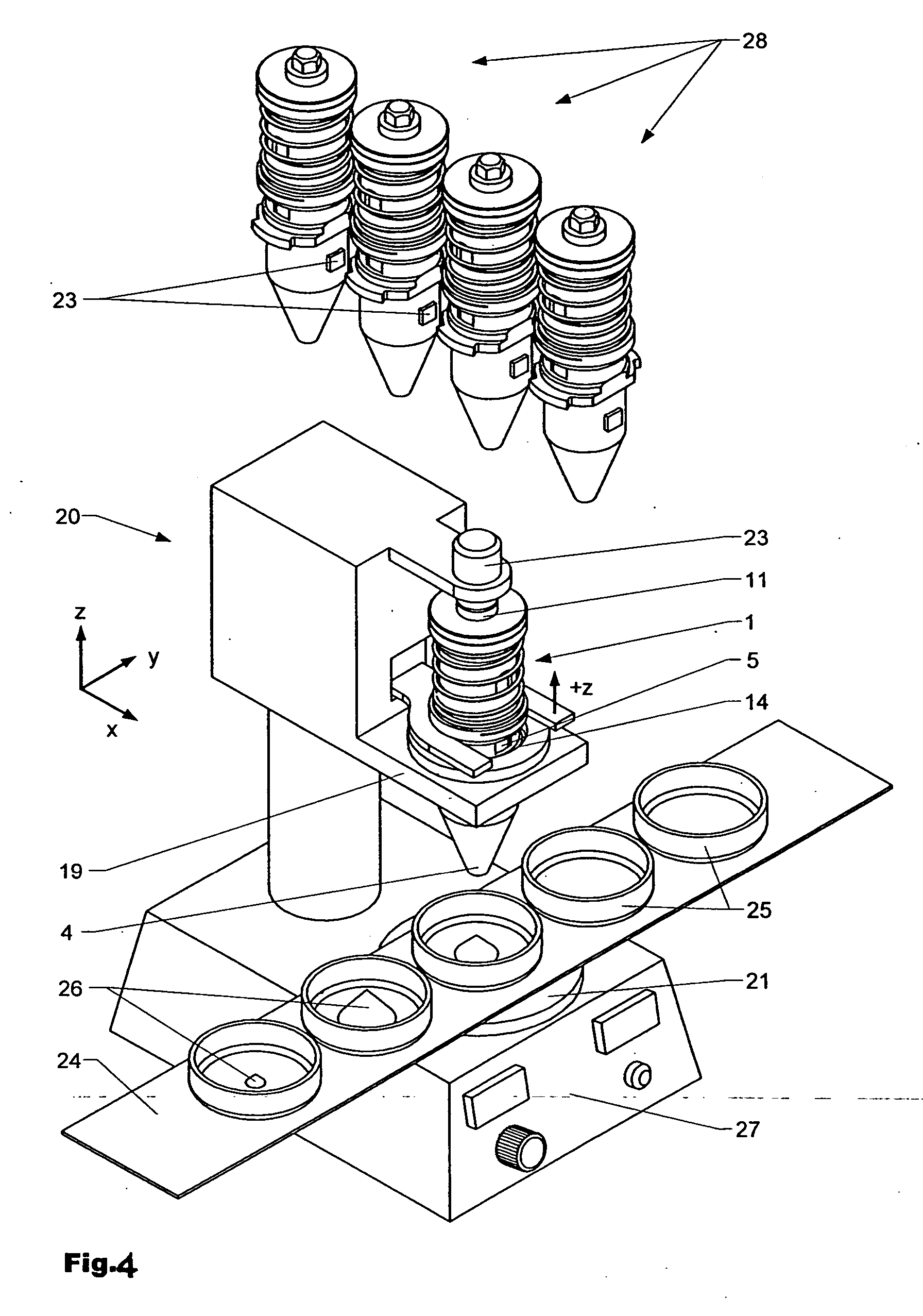
[0044] Reference is now made in detail to embodiments of the invention, examples of which are illustrated in the accompanying drawings.

[0045]FIG. 1 shows a dispensing device 1 in a perspective view and FIG. 2 shows the dispensing device 1 according to FIG. 1 in a disassembled manner such that the internal of the dispensing device is visible. FIG. 3 shows a cross-cut view along line DD through the dispensing device 1 according to FIGS. 1 and 2.

[0046] The dispensing device 1 comprises a housing 2 surrounding a compartment 3 suitable to receive material to be dispensed. At the lower end the housing 2 comprises a gate valve opening 4 which is in closed position sealingly covered by a blend 5 which is supported by a rim of the opening 4. The blend 5 is arranged retractable in a notch 6 extending radially with respect to the opening along the outside of the housing 2. The notch 6 acts as a guiding means for the blend 5. The blade like blend 5 is made in the herein shown embodiment out o...


PUM

PropertyMeasurementUnit
Scaling lawaaaaaaaaaa
Elasticityaaaaaaaaaa

Abstract

The invention is directed to a dispensing unit suitable to precisely dispense material in powdery and / or granular form. The dispensing device comprises an gate valve opening sealingly closed by a blend. A control unit, which is interconnected to a scaling device, controls the opening of the gate valve opening by the position of the blend. The precise amount of the material is adjusted in relation to the signal of the scaling device.

Description

FIELD OF THE INVENTION [0001] The present invention relates to an apparatus and a method for dispensing material, especially small amounts of solid material in powdery or granular form. BACKGROUND OF THE INVENTION [0002] In various industries, such as the chemical and the pharmaceutical industry handling of non-liquid materials in solid or powdery form is used for preparing mixtures, drugs, tests, in-process products or final products. Several dispensers for handling powdery materials are known from prior art and it is inherent to those devices that in general they are not suitable to precisely dispense different amounts of material, especially when the amount of material to be dispensed is small (e.g. in the range of milligrams). Most important, these devices are not suitable to dispense powdery materials if the starting amount is very limited, such as e.g. 30 mg or less. However, in the chemical and the pharmaceutical industry, for research, development and production, it is impor...

Claims


Application Information

Patent Timeline
IPC IPC(8): B65B3/26
CPCB01L3/021B01L2200/0657G01G13/02B01L2300/021B01L2300/049B01L2200/143
Inventor PLUVINAGE, LOICVALELLA, ANTONIOBERINI, GIAN-LUIGI
Owner FREESLATE
Learn More