Systems and methods for installation, design and operation of groundwater monitoring systems in boreholes

a monitoring system and underground cavern technology, applied in the direction of borehole/well accessories, fluid removal, survey, etc., can solve the problems of hydrostatic flooding, leakage of storage tunnels, and potential collapse, and the chemical properties of the underground caverns or tunnels will likely chang

Inactive Publication Date: 2007-01-11
BESST +1
View PDF10 Cites 37 Cited by
  • Summary
  • Abstract
  • Description
  • Claims
  • Application Information

AI Technical Summary

Benefits of technology

[0036] The present invention also provides a method of installing a system for monitoring groundwater pressure and quality surrounding a borehole defined within ground. The method includes providing a central pipe and at least one riser pipe arrangement to the central pipe with a centralizer. Each riser pipe arrangement comprises a riser pipe and a filter coupled to the riser pipe at a distal end. A sensor arrangement is included within each riser pipe. Each sensor arrangement comprises a sensor isolation tip that comprises one or more O-rings around an outer surface of the sensor isolation tip and adjacent to the riser pipe. The sensor arrangement further comprises a removable sensor communicatively coupled to the control system and to a distal end of the sensor isolation tip, and a groundwater sample return line coupled to the sensor isolation tip and comprising at least one inlet at a distal end and an outlet at a proximal end outside the borehole. The method includes moving the central pipe into the borehole and moving at least one riser pipe arrangement into the borehole by moving it along the central pipe. The method further includes moving a very fine-grained filter pack material through the central pipe such that it is between each filter and adjacent walls of the borehole and moving a sensor arrangement into each riser pipe. A pressurized gas is provided into each riser pipe to force groundwater therein through the at least one inlet and through the groundwater sample return line. Each sensor is communicatively coupled to a control system outside the borehole.

Problems solved by technology

These caverns and tunnels may become subject to various stresses that could lead to leakage of surrounding fluids into the caverns or tunnels potentially resulting in hydraulic flooding as well as potential collapse due to various stress-related factors.
These monitored changes can also signal potential problems with regard to the stabilities within rock media surrounding the access tunnel, thereby indicating a potential need for worker evacuation from the access tunnels.
LNG that leaks from the storage tunnels will likely change both chemically and physically over a short period of time due to decreasing pressure and differing temperature from an immiscible liquefied phase to a dissolved aqueous phase within the surrounding groundwater fluids.
These leaks could then dramatically affect aquatic ecology of the surrounding ocean environs and pose significant cost burden for tunnel reparations, as well as translate into replacement costs for the lost LNG.
LNG leakage also poses a significant health and safety risk.
If there is enough oxygen within these air spaces and pockets, explosive flashes may occur due to electrical spark, welding activity, or even heat generated from cigarette embers.
Keeping waters from different borehole depths separate, and transporting the water to the surface, is difficult, time-consuming and costly.
As an example, some of these systems only allow a single port in a multi-level monitoring system to be purged and sampled for groundwater at any one time.
Another feature concerning conventional monitoring technologies is that groundwater sampling devices are typically characterized by valve mechanisms that can become easily jammed or clogged with sediment—adding maintenance and repair time and therefore more time and cost for obtaining groundwater samples.
Another disadvantage of conventional groundwater monitoring systems is with respect to the removal rate of “old water” from the system before each sampling event.
Given that many of these sampling ports in tunnel systems are deep with respect to ground surface and that numerous time-consuming repetitions of vial entry and removal are required during the purging process, the result is that many hours up to weeks of time may be required for purging a single port.
However, being that the groundwater access pipes are typically of small diameter, the use of a parallel tube configuration with a gas displacement pump requires that the tubing for the gas-in line and the water return line are very small.
This therefore limits the amount of water volume that can be removed with each pump stroke.
These devices are susceptible to plugging from water-borne sediment via intrusion into the sealing mechanisms and mechanical works inside each type of valve.
Once sediment has intruded, some of these devices are difficult to clean out and repair, and may require removal of the entire monitoring system to access the impaired valve.

Method used


Image

  • Systems and methods for installation, design and operation of groundwater monitoring systems in boreholes
  • Systems and methods for installation, design and operation of groundwater monitoring systems in boreholes
  • Systems and methods for installation, design and operation of groundwater monitoring systems in boreholes

Examples


Embodiment Construction

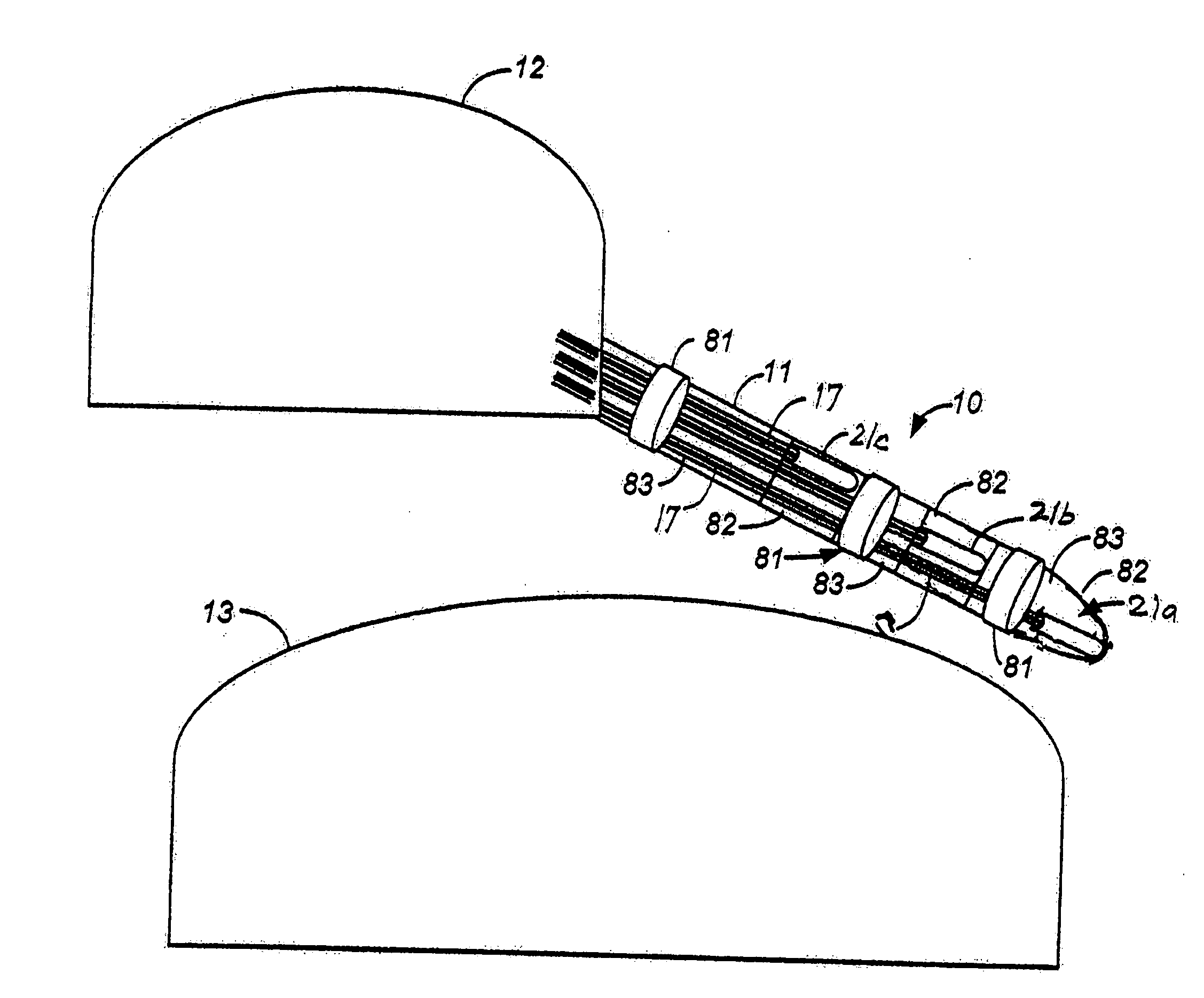
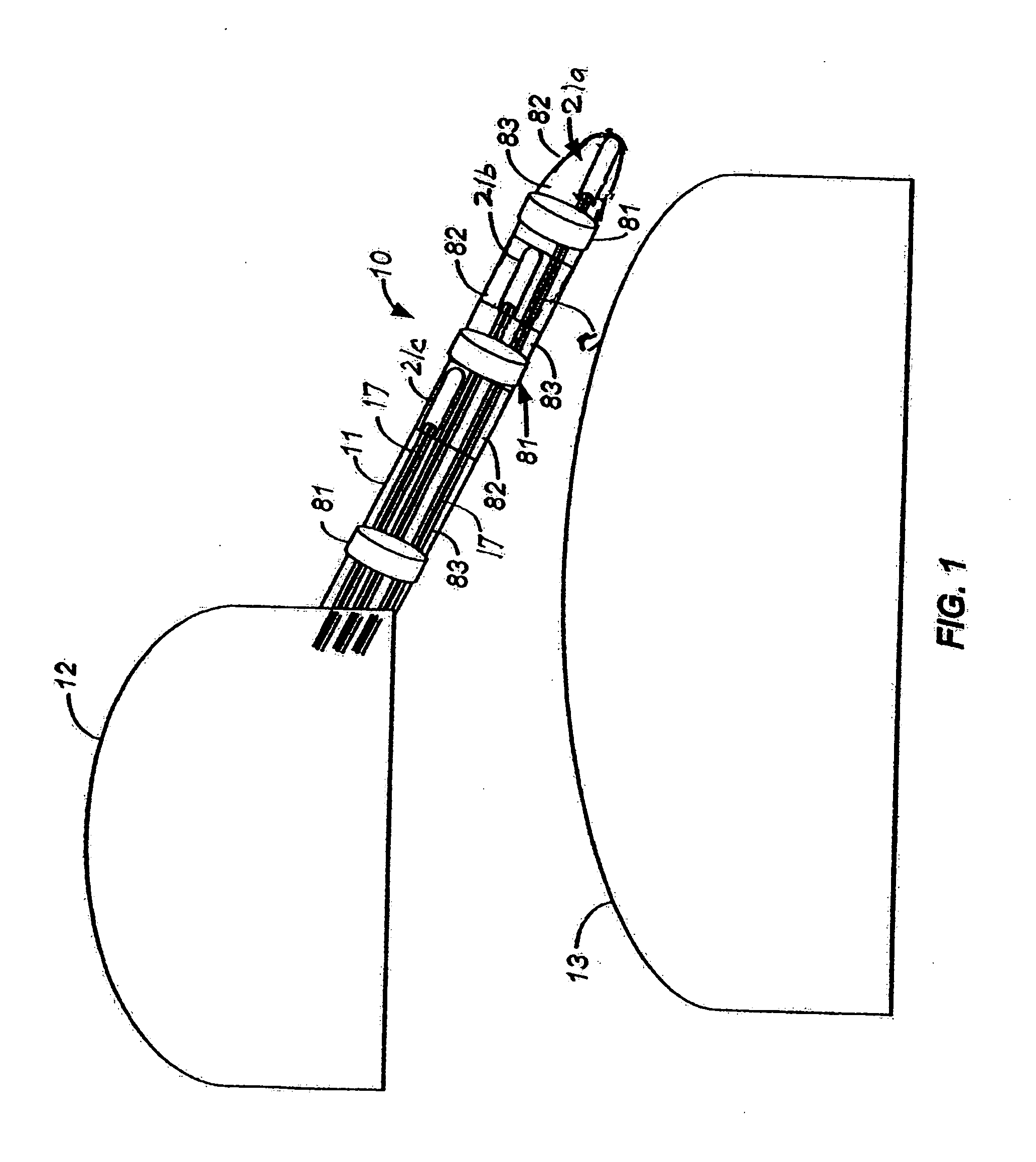
[0058] The present invention provides systems and methods for monitoring groundwater within boreholes within the ground. Generally, the boreholes are created within rock media adjacent to manmade tunnels or caverns. Sensors are placed within access pipes (riser pipes) in the boreholes to monitor hydraulic pressure in order to sense potential changes within the ground thereby leading to potential problems with the tunnels or caverns. Additionally, groundwater samples may be obtained from the boreholes and tested for quality to watch for other potential problems, such as gas leakage or other radio activity, depending upon what is in the cavern or tunnel. For clarity and simplicity, the present invention will be described with reference to tunnels 13 that are defined or created under a minimum of 600 feet of ocean water and beneath the ocean floor. These tunnels are used to store liquefied natural gas (LNG) comprised of methane and butane. Hydraulic pressure from the ocean water column...


PUM


Abstract

Systems and methods for installation and operation of a groundwater monitoring system in a borehole of any angle using a coaxial gas displacement pump with a unique O-ring assembly that serves as a two-position valve for groundwater purging and sampling and also as a housing and sealing mechanism for isolating an optical pressure sensor. The optical sensor measures in-situ hydraulic pressure directly subjacent and adjacent to the surrounding rock fractures and sediment pores without hydraulic interferences from potentiometric equilibration lag time from recovery fluid pressure inside a borehole, in a zone above the optical sensor, or on the inside of a riser pipe that rises to the ground surface.

Description

BACKGROUND OF THE INVENTION [0001] 1. Field of the Invention [0002] The present invention relates to monitoring underground caverns or tunnels, and more particularly, to monitoring underground hydraulic and water quality conditions within various bores extending from and located in close proximity to underground caverns and tunnels. [0003] 2. Description of the Prior Art [0004] For the purpose of tunnel construction worker safety and post-construction structural integrity and safety, it is often desirable and required by laws, regulations, etc. to monitor hydraulic changes, which may change rapidly, in saturated fractured rock media and sediments in the earth materials surrounding these underground structures. Additionally, it may be desirable and required by laws, regulations, etc. to monitor groundwater quality within these fractured rock media and sediments. For example, underground caverns and tunnels may exist for a variety of purposes, including the storage of liquefied natura...

Claims


Application Information

Patent Timeline
Patent Type & Authority Applications(United States)
IPC IPC(8): E21B47/00
CPCE21B47/00E21B43/02
Inventor HELLER, NOAHATSUMI, HIROYOKITOIDA, MASARUCHINO, TORU
Owner BESST
Why Eureka
Try Eureka