Method for driving liquid crystal panel, and liquid crystal display device

a liquid crystal display and liquid crystal panel technology, applied in static indicating devices, instruments, optics, etc., can solve the problems of increased power consumption, complicated construction, and reduced image quality, so as to achieve the desired transmittance, the effect of improving image quality such as reducing a contrast value or the lik

Inactive Publication Date: 2007-01-11
MITSUBISHI ELECTRIC CORP
View PDF3 Cites 21 Cited by
  • Summary
  • Abstract
  • Description
  • Claims
  • Application Information

AI Technical Summary

Benefits of technology

[0010] In the low temperature range where the peripheral temperature of the liquid crystal panel is low, it is easy to achie

Problems solved by technology

However, when a graphic image such as a figure or the like is displayed, degradation in image quality such as blurring of the boundary of an image, ghost, cross-talk or the like may be visually recognized.
Furthermore

Method used


Image

  • Method for driving liquid crystal panel, and liquid crystal display device
  • Method for driving liquid crystal panel, and liquid crystal display device
  • Method for driving liquid crystal panel, and liquid crystal display device

Examples


embodiment 1

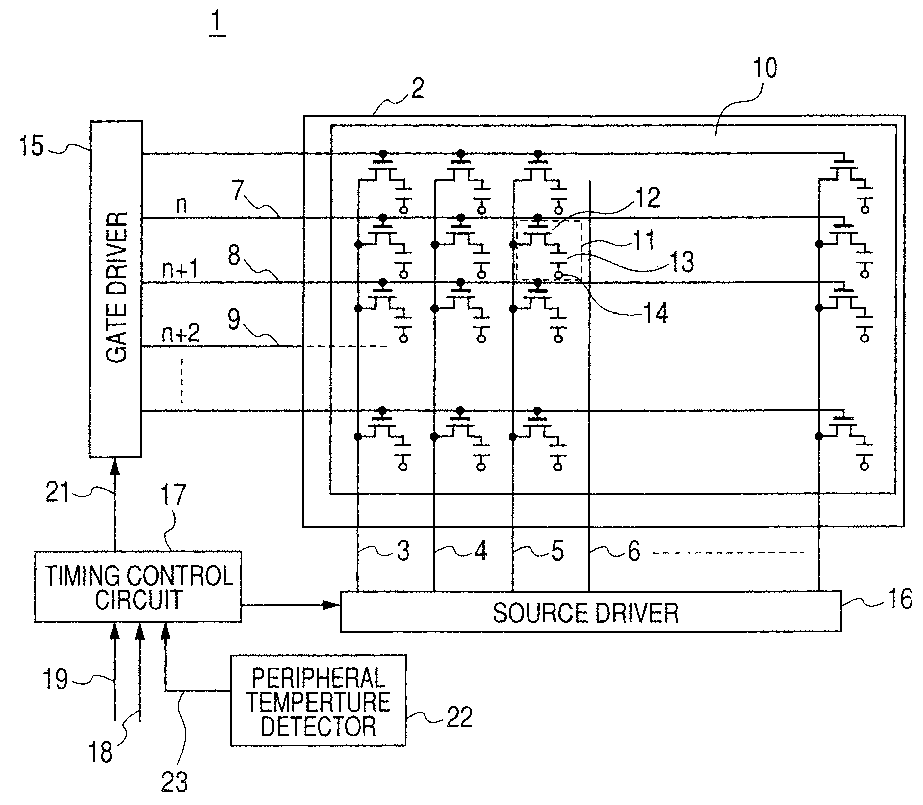
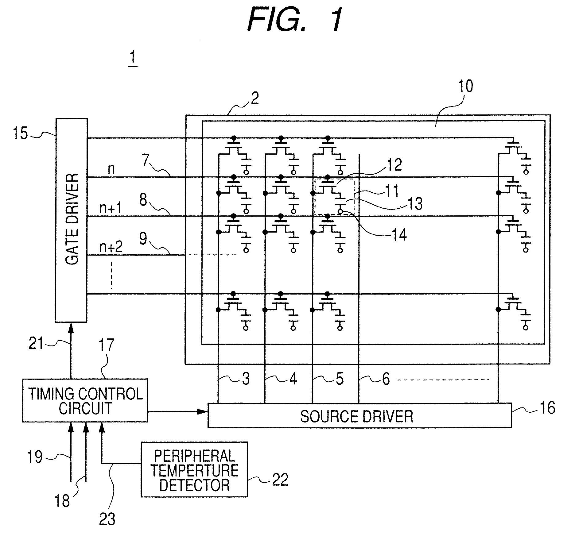
[0017]FIG. 1 is a diagram showing a system construction of a liquid crystal display device 1 adopting a liquid crystal panel driving method according to Embodiment 1 of the present invention. In FIG. 1, a normally black liquid crystal panel 2 includes an active matrix substrate 20 constructed by plural data wires 3, 4, 5, 6, etc. and plural horizontal scan wires 7, 8, 9, etc. which are cross to one another and arranged in a matrix form, a counter substrate (not shown) facing the active matrix substrate 10, the active matrix substrate 10 and the counter substrate being attached to each other through a gap, and liquid crystal (not shown) is disposed in the gap so as to be sandwiched between the active matrix substrate 10 and the counter substrate. Here, in order to simplify the description, the construction of specific one pixel portion will be described in detail, and the overall liquid crystal panel 2 will be described later.

[0018] A pixel portion 11 indicated by a broken line is d...

embodiment 2

[0034] First, the system construction of a liquid crystal display device adopting a method of driving a liquid crystal panel according to an embodiment 2 is the same as the construction shown in FIG. 1 in the embodiment 1, and thus the detailed description is omitted. In the following description, the operation of the timing control circuit 17 in the low temperature range will be described with reference to the timing chart of FIG. 4.

[0035] Here, when the peripheral temperature exceeds a predetermined temperature (for example, 0° C.) and thus the temperature information 23 output from the peripheral temperature detector 22 indicates a value of the normal temperature range, the timing control circuit 17 executes the same control as the operation in the normal temperature range described in the above-described embodiment 1, that is, carries out the one-frame inversion driving operation in which the polarity of the image data signal applied to the data wire 5 is inverted every frame, ...

embodiment 3

[0045] First, the system construction of a liquid crystal display device using a method for driving a liquid crystal panel according to an embodiment 3 is the same as the construction of FIG. 1 in the embodiment 1, and thus the detailed description is omitted from the following description. The operation of the timing control circuit 17 in the low temperature range will be described hereunder with reference to the timing chart of FIG. 4.

[0046] When the peripheral temperature exceeds a predetermined temperature (for example, 0° C.) and the temperature information 23 output from the peripheral temperature detector 22 indicates the value of the normal temperature range, the timing control circuit 17 executes the same control as the operation in the normal temperature range described in the embodiment 1, that is, the timing control circuit 17 executes the one-frame inversion driving operation in which the polarity of the image data signal applied to the data wire 5 is inverted every fr...


PUM


Abstract

A method for driving a liquid crystal panel that includes horizontal scan wires, data wires, pixel electrodes surrounded by the horizontal scan wires and the data wires; and switching elements connected to the pixel electrodes, wherein the switching elements are controlled by a gate selection signal and during a on-time period, the switching elements is turned on, and an image data signal output from the data wires is supplied to the pixel electrodes by the switching elements. The method includes: detecting a peripheral temperature of the liquid crystal panel; and controlling the gate selection signal so that when the detected temperature is within a normal temperature range, the on-time period is set to a first gate selection period, and that when the detected temperature is within a low temperature range, the on-time period is set to a second gate selection period longer than the first gate selection period.

Description

BACKGROUND OF THE INVENTION [0001] 1. Field of the Invention [0002] The present invention relates to a method for driving a liquid crystal panel, and a liquid crystal display device, and particularly to a method for driving an active matrix type liquid crystal panel that can surely display an image irrespective of peripheral temperature of the liquid crystal panel, and a liquid crystal display device. [0003] 2. Description of the Related Art [0004] Recently, liquid crystal display devices have been applied for various kinds of applications under various environments. For example, with respect to peripheral temperature, it is required that these devices are excellently operated at from a high-temperature to a low-temperature. [0005] Furthermore, TFT (Thin Film Transistor), TFD (Thin Film Diode), etc. are known as switching elements for the active matrix type liquid crystal display devices. Particularly, from the viewpoint of the image quality, TFT has been recently mainly used. In ge...

Claims


Application Information

Patent Timeline
IPC IPC(8): G09G3/36
CPCG09G5/001G09G2310/0254G09G2330/021G09G2320/041G09G2320/0261G09G3/36G02F1/133G09G3/20
Inventor NAKANISHI, KUNIFUMITERAGAKI, TOMOYA
Owner MITSUBISHI ELECTRIC CORP
Why Eureka
Try Eureka