Eureka AIR delivers breakthrough ideas for toughest innovation challenges, trusted by R&D personnel around the world.

Optimizing use and performance of optical systems implemented with telecentric on-axis dark field illumination

Inactive Publication Date: 2007-01-11
ELECTRO SCI IND INC
View PDF18 Cites 13 Cited by
  • Summary
  • Abstract
  • Description
  • Claims
  • Application Information

AI Technical Summary

Benefits of technology

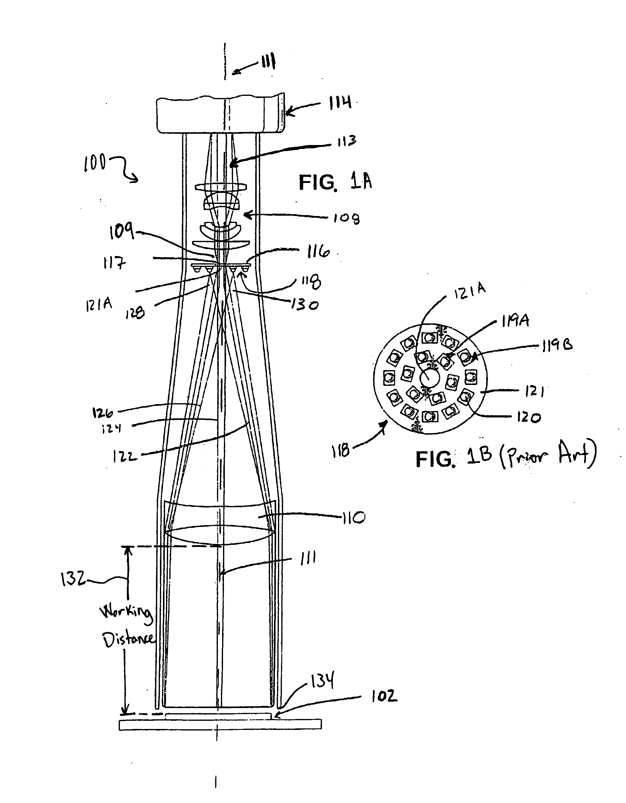
[0014] The embodiments disclosed herein provide systems and methods for imaging a planar specular object such as a semiconductor wafer. In one embodiment, an imaging system for imaging a defect on a planar specular object includes a telecentric lens having a sufficiently aspherical surface such that the telecentric lens is substantially corrected for an optical aberration. The imaging system also includes a telecentric stop including an aperture therein to block light reflected from the planar specular object while allowing light reflected from the defect to pass through the aperture. The imaging system also includes a second lens group having a system stop positioned between the telecentric stop and the second lens group, the second lens group being substantially corrected for the optical aberration independent of the telecentric lens.

Problems solved by technology

Heat dissipation is generally a major hurdle in achieving a design objective of achieving compact packaging.
Demands on the illumination system place demands upon the power supply system and thereby exacerbate problems of thermal dissipation within a compact package.
If this range could be extended by an order of magnitude, focusing and setup of the system would be trivial compared to existing systems.

Method used


Image

  • Optimizing use and performance of optical systems implemented with telecentric on-axis dark field illumination
  • Optimizing use and performance of optical systems implemented with telecentric on-axis dark field illumination
  • Optimizing use and performance of optical systems implemented with telecentric on-axis dark field illumination

Examples


Embodiment Construction

[0027] Systems and methods are provided for illuminating and forming an image of a predominantly planar and specular surface such that deviations from planarity or specularity of the surface being imaged are reproduced with enhanced contrast. According to one embodiment, an increased working distance range is provided to account for variations in the surface being imaged and / or variations in a distance between the surface and an identification (ID) system.

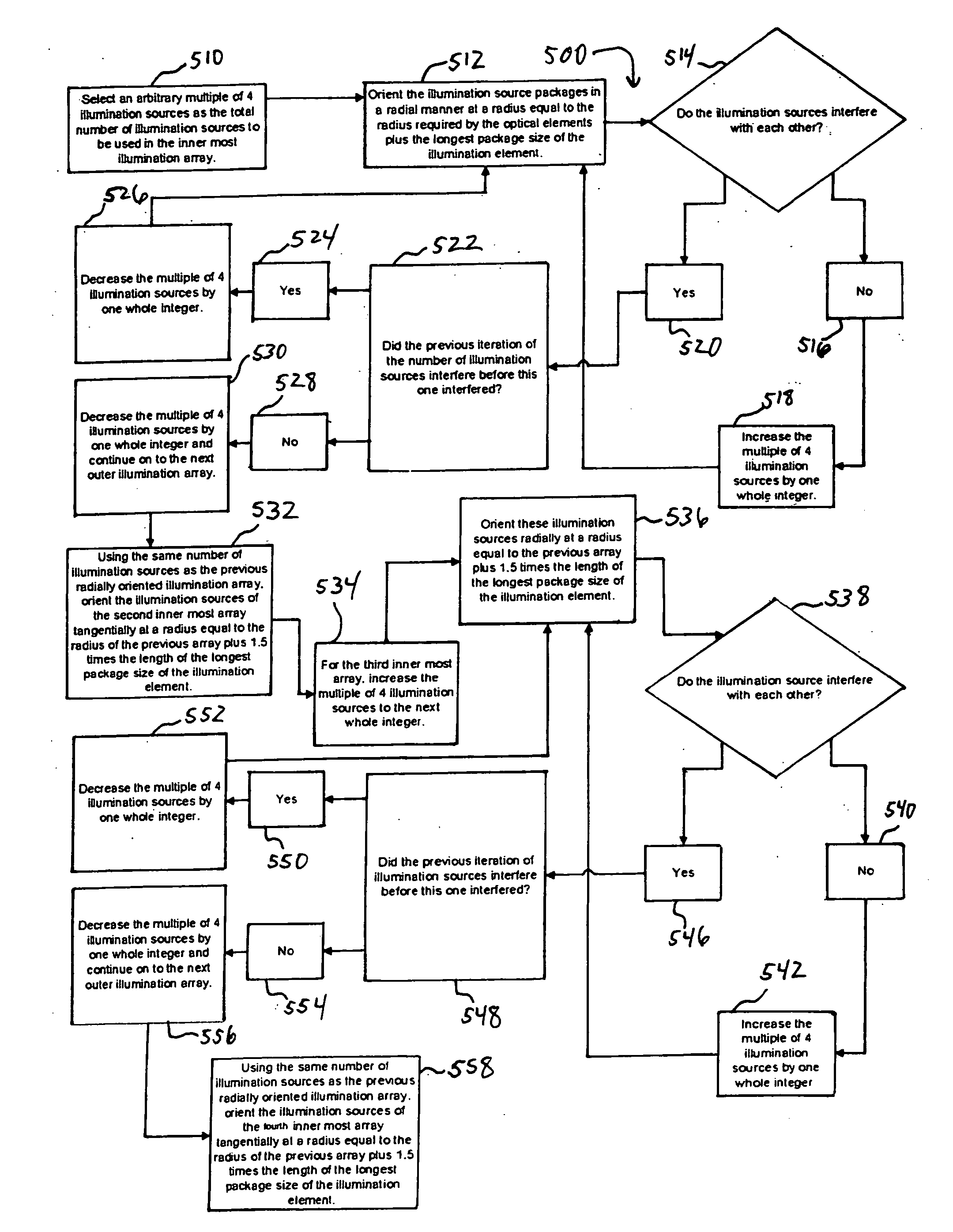
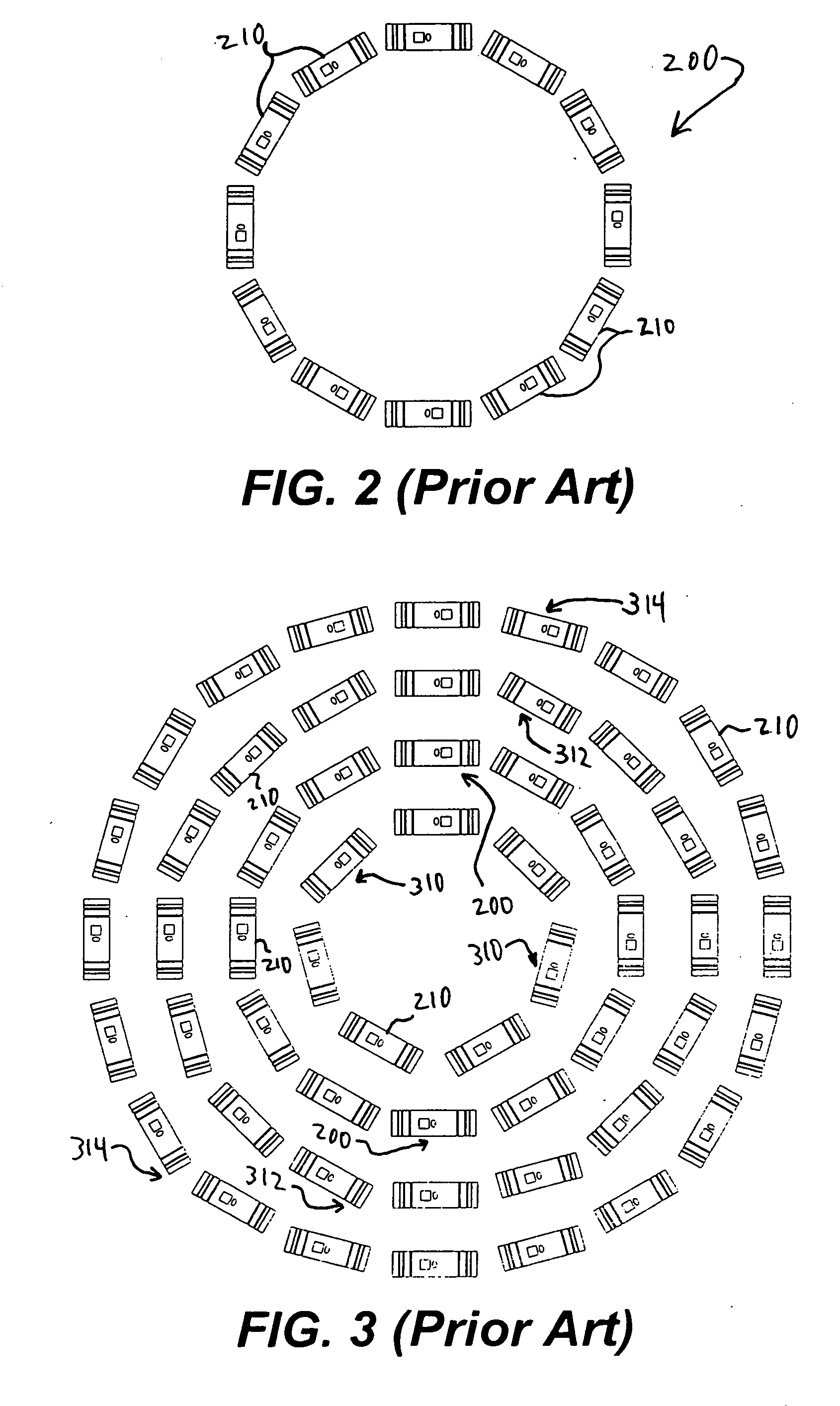
[0028] In addition, or in another embodiment, concentric circular arrays of illumination sources are arranged for increased illumination without increasing the diameters of the respective arrays. In one embodiment, a method is provided for aligning concentric illumination arrays with a surface to be imaged so as to reduce the angle of incidence. In addition, or in other embodiments, a system includes a front lens and a rear lens group that are independently well corrected for perturbations such that the magnification of the system...


PUM


Abstract

Systems and methods are provided for imaging a planar specular object such as a semiconductor wafer. In one embodiment, an imaging system for imaging a defect on a planar specular object includes a telecentric lens having a sufficiently aspherical surface such that the telecentric lens is substantially corrected for an optical aberration. The imaging system also includes a telecentric stop including an aperture therein to block light reflected from the planar specular object while allowing light reflected from the defect to pass through the aperture. The imaging system further includes a lens group having a system stop positioned between the telecentric stop and the lens group. The lens group is substantially corrected for the optical aberration independent of the telecentric lens.

Description

RELATED APPLICATION [0001] This application claims the benefit under 35 U.S.C. § 119(e) of U.S. Provisional Application No. 60 / 697,904, filed Jul. 8, 2005, which is hereby incorporated by reference herein in its entirety.TECHNICAL FIELD [0002] This disclosure relates to imaging optics and associated illumination systems. In particular, this disclosure relates to systems and methods for improving telecentric on-axis dark field illumination. BACKGROUND INFORMATION [0003] There is a class of semiconductor products that are predominantly planar and specular (flat and shiny). It is frequently necessary or desirable to image these devices in such way that even minor deviations from planar and specular are imaged with adequate contrast. One such class of products are semiconductor wafers that may be provided with indicia that indicate, among other things, wafer number and manufacturer. These indicia are defects in the surface of the wafer and are typically a matrix of laser etched pits. Th...

Claims


Application Information

Patent Timeline
IPC IPC(8): G03B17/00
CPCG01N21/47G02B13/22G01N2021/8822G01N21/9501G01N21/88H01L22/00
Inventor BALDWIN, LEOEMERY, JOSEPH
Owner ELECTRO SCI IND INC
Why Eureka
Eureka Blog
Learn More