
Infrared suppressive material

Inactive Publication Date: 2007-01-11
WL GORE & ASSOC INC
View PDF4 Cites 82 Cited by
  • Summary
  • Abstract
  • Description
  • Claims
  • Application Information

AI Technical Summary

Benefits of technology

[0012] The current invention overcomes the obstacles of the previous art by providing a layer adjacent to the textile layer that enables reduced nIR reflection, without substantially altering visual camouflage. Moreover, specific embodiments of the current invention allow for the ability to create camouflage materials that possess a favorable balance of durable environmental protection and appropriate nIR camouflage. Surprisingly, it was found the current invention enables the ability to achieve acceptable visual camouflage, particularly on light colors, and reduced nIR reflectance. More surprisingly, some constructions of the current invention were discovered to have significantly improved durability of nIR camouflage.

Problems solved by technology

A disadvantage to this technique is that the carbon can negatively impact the desired visible shade of the camouflage textile and frequently results in a compromise between achieving appropriate visible and nIR camouflage, particularly in environments which require extremely light shades like the desert.
In addition, topically treating textiles with such a carbon finish results in a textile material with poor nIR camouflage durability, as the topical carbon finishing can readily wash and / or wear off in use.
A further challenge in creating camouflage textiles which are suitable for the applications described is the need for comfort of the user.
However, providing environmental protection by coating or lamination of liquidproof, breathable films or coatings can also affect the visible and nIR camouflage properties of the textile.
For example, in the specific case of a liquidproof, breathable film comprising microporous PTFE, the PTFE film often increases the overall reflectivity in the nIR spectrum, and possibly the visible spectrum as well, resulting in undesirable tradeoffs between durable environmental protection and nIR camouflage.
Further features such as durable environmental protection in these improved construction have also been unavailable.

Method used


Image

  • Infrared suppressive material
  • Infrared suppressive material
  • Infrared suppressive material

Examples


example 1

[0054] Monolithic nIR suppressive layer samples were prepared from polyurethane and additives. Specifically, polyurethane samples were prepared as taught in U.S. Pat. No. 4,532,316. The pre-polymer described was heated at 150° C. to fluid form, and 10% titanium dioxide powder (DuPont Chemicals, Wilmington, Del.) was dispersed in the polymer by hand mixing to form a homogeneous mixture. The cool, TiO2-filled pre-polymer was then heated at 150° C. for one hour and divided into five portions. Carbon black (Vulcan XC72, Cabot Corporation, Boston, Mass.), in five different concentrations of 0.01%, 0.05%, 0.1%, 0.5% and 1.0% by weight was added to each portion of the pre-polymer and hand mixed until it appeared homogenous. Films were formed from each of these fluids, whereby the heated polyurethane pre-polymer portions were cast at 4 mil thickness using a manual drawn down technique and draw down bars. These films were moisture cured for 48 hours at ambient temperature.

[0055] Average ref...

example 2

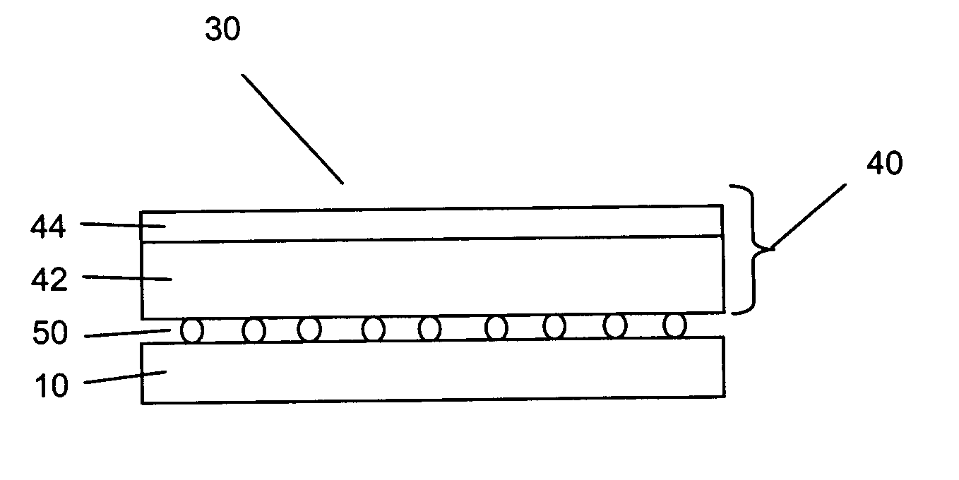
[0056] A construction of each of the five near infrared suppressive layer samples formed in Example 1 and a Day Desert Camouflage Nylon textile (Style #131971, Milliken & Company, Spartanburg, S.C.), was made by stacking each film with the textile material in an unbound layered construction and clamping in an embroidery hoop. The light tan portion of the camouflage textile pattern was used for reflectance measurements on all constructions that include a textile, unless otherwise specified. The average reflectance of each of the five constructions of this example was measured in the 400-700 nm and the 720-1100 nm wavelength ranges. Results are reported in Table 2 as Examples 2a-2e.

example 3

[0061] A microporous ePTFE membrane measuring 0.001 inch thick (0.2 μm nominal pore size, mass of 20 g / m2, obtained from W. L. Gore & Associates, Inc.) was coated with carbon black (Vulcan XC72, Cabot Corporation, Boston, Mass.) using a fluorocarbon polymer binder and wetting agents. The binder system was formulated by mixing 2.6 g of Witcolate ES2 (30% solution) (obtained from Witco Chemicals / Crompton Corporation, Middlebury, Conn.), 1.2 g of 1-Hexanol (Sigma-Aldrich Chemical Corporation, St. Louis, Mo.), and 3.0 g of fluoropolymer (AG8025, Asahi Glass, Japan) in 13.2 g of deionized water. 0.015 g of Carbon black was added to the binder system. The mixture was sonicated for 1 minute. The membrane was hand coated with the mixture using a roller to a coating weight of approximately 3 g / M2. The coated membrane was cured at 185° C. for 2.5 minutes. The moisture vapor transmission rate of the coated membrane was measured to be 45,942 g / m2 (24 hours).


PUM


Abstract

Near infrared suppressive layers are described having an average reflectance between 9% and 70% in the wavelength range from about 400 nm to 700 nm, and an average reflectance of less than or equal to 70% in the wavelength range from about 720 nm to 1100 nm. Additionally, articles made from such near infrared layers are described, wherein the articles provide desirable reduced nIR reflection without substantially altering the visual shade of the overall article.

Description

FIELD OF THE INVENTION [0001] This invention relates to infrared suppressive materials that suppress near infrared radiation while also providing good shade retention in the visible wavelength spectrum. BACKGROUND OF THE INVENTION [0002] Camouflage textile materials used by hunters and by the military typically provide camouflage in the visible region of the electromagnetic radiation spectrum (400-700 nm). The terms “visible” and “visible camouflage” will be used herein to denote a material that exhibits sufficient reflectance in the visible region of the electromagnetic spectrum (wavelength from 400 nm to 700 nm) so that it can be seen by the unassisted human eye. The terms “shade,”“shade variation,” and the like, refer to variations in color, such as determined by MIL-PRF-32142, MIL-DTL 31011B and 31011AATCC. An acceptable shade variation is one which the color and appearance of the camouflage printed laminate shall match the standard sample when viewed using AATCC Evaluation Proc...

Claims


Application Information

Patent Timeline
IPC IPC(8): A41G1/00A01N3/00
CPCF41H3/02Y10T442/259Y10T442/2139
Inventor HOLCOMBE, JOHN D.NANDI, MANISH K.
Owner WL GORE & ASSOC INC
Learn More