
Manufacturing methods of electromagnetic-wave shielding and light transmitting window material, display panel, and solar battery module

Inactive Publication Date: 2007-01-18
BRIDGESTONE CORP
View PDF1 Cites 27 Cited by
  • Summary
  • Abstract
  • Description
  • Claims
  • Application Information

AI Technical Summary

Benefits of technology

[0027] An object of the present invention is to provide methods for manufacturing an electromagnetic-wave shielding and light transmitting window material and a display panel, in which the adhesion can be rapidly performed as compared to that performed in the past.
[0030] When the induction heating is performed in the step of heating the adhesive resin for adhesion, the adhesive resin can be heated in a short period of time as compared to that in the past, and as a result, the manufacturing efficiency of the electromagnetic-wave shielding and light transmitting window material and the display panel can be improved.
[0031] An object of the present invention is to provide a method for manufacturing a solar battery module in which heating of a laminate can be rapidly performed in a cell sealing step as compared to that in the past.
[0033] Since the heating step for sealing the solar battery cells is performed by the induction heating, the laminate can be heated within a short period of time as compared to that in the past, and as a result, the manufacturing efficiency of the solar battery module can be improved.

Problems solved by technology

I. In recent years, concomitant with increase in demand of OA devices, communication devices, and the like, electromagnetic waves generated therefrom has begun to be considered as a problem.
That is, influence of electromagnetic waves on human bodies is of concern, and in addition, malfunctions of precision apparatuses caused by electromagnetic waves have become problems.
Heretofore, the step of heating the laminate, which is performed when the solar battery cells are sealed, has been performed using a constant-temperature bath maintained at a predetermined temperature; however, it takes time to increase the temperature of the laminate.

Method used


Image

  • Manufacturing methods of electromagnetic-wave shielding and light transmitting window material, display panel, and solar battery module
  • Manufacturing methods of electromagnetic-wave shielding and light transmitting window material, display panel, and solar battery module
  • Manufacturing methods of electromagnetic-wave shielding and light transmitting window material, display panel, and solar battery module

Examples


example 1

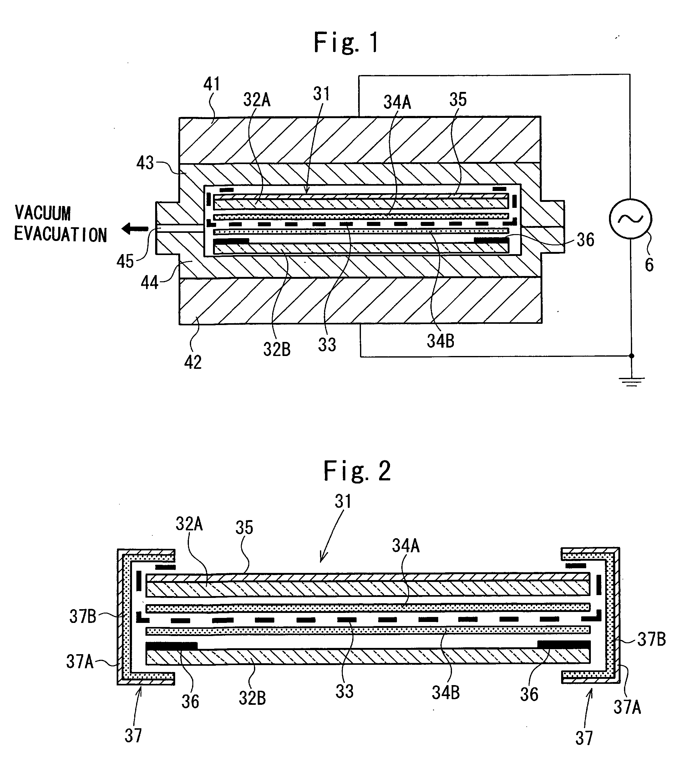
[0092] By using 2 glass plates having a thickness of 2.0 mm as a front surface-side transparent substrate, after high-frequency heating electrodes were extended from an electromagnetic-wave shielding etched mesh film, this film was laminated by two adhesive resin films located at a top and a bottom side. Subsequently, after the laminate thus formed was sandwiched by two silicone rubber sheets, and vacuum deaeration was performed, heating was performed at a temperature of 90° C. for 10 minutes, so that pre-pressure bonding was performed. Then, after pressing was performed using pressing plates, a high frequency of 13.56 MHz was applied to the pressing plates or the electrodes extended from the etched film to perform high-frequency heating, and in addition, heating was also performed by heaters provided for the pressing plates, so that cross linking of adhesive interlayer films was performed at 130° C. for a predetermined time.

After the heating, a peeling test was performed, and it ...

example 2

[0122] After each film was formed from an EVA resin composition containing the following components, embossing was performed, so that a transparent EVA film was manufactured.

[0123] [Components of EVA Resin Composition for Transparent EVA Film (Parts by Weight)]

[0124] EVA resin: 100

[0125] Cross-linking agent (1,1-bis(t-butylperoxy)-3,3,5-trimethyleyelohexane): 2.0

[0126] Silane coupling agent (γ-methacryloxypropyltrimethoxysilane): 0.5

[0127] Anti-yellowing agent: 0.1

[0128] Cross-linking auxiliary agent (triallyl isocyanurate): 2.0

[0129] Ultraviolet absorber (2-hydroxy-4-octylbenzophenone): 0.03

[0130] The transparent EVA films thus formed were used as a rear surface side sealing film and a front surface-side sealing film, and solar battery cells (silicon power generation elements) were sealed between a glass plate having a thickness of 3 mm and a back cover 2 made of a fluorinated polyethylene film having a thickness of 38 μm, so that the solar battery was formed. After electrod...


PUM

PropertyMeasurementUnit
Currentaaaaaaaaaa
Currentaaaaaaaaaa
Digital informationaaaaaaaaaa

Abstract

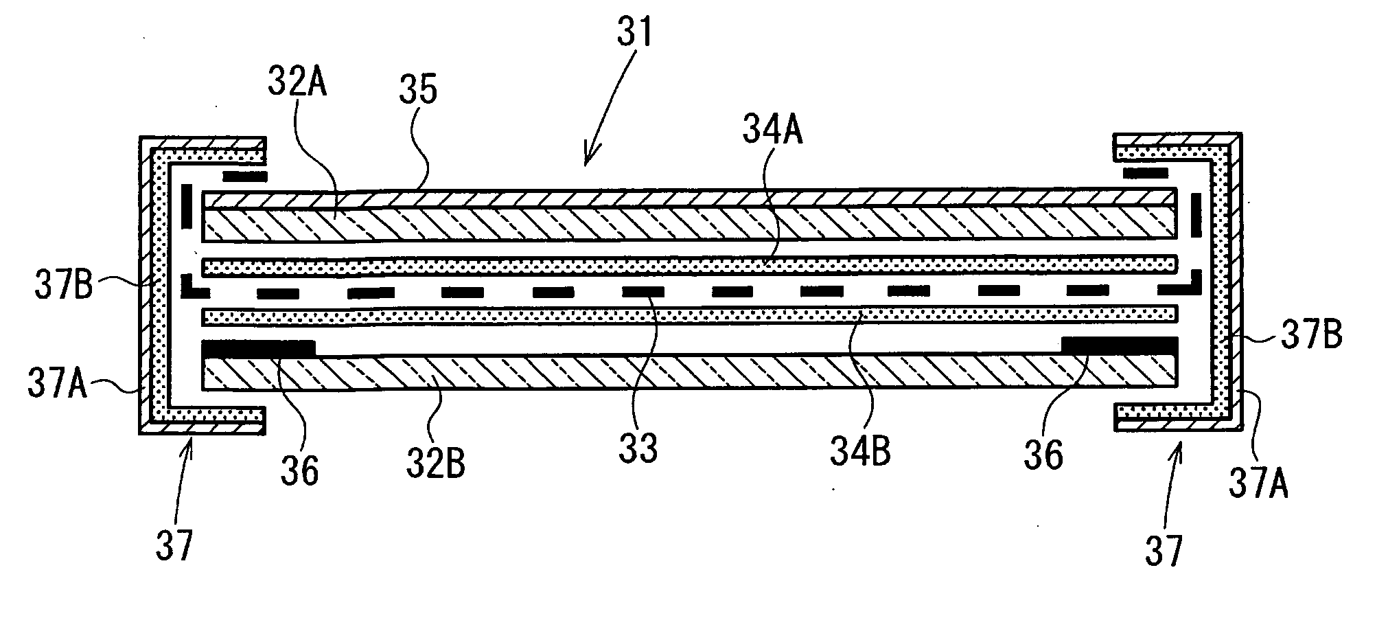
In order to decrease the time (adhesion time in an adhesion step) for manufacturing an electromagnetic-wave shielding and light transmitting window material and a display panel, a top mold 43 and a bottom mold 44, which are made of a synthetic resin having high heat resistance, are disposed between a top and a bottom pressing plate 41 and 42, and a laminate is disposed between the molds 43 and 44. This laminate is formed of a transparent substrate 32A provided with an anti-reflection film 35, an adhesive interlayer film 34A used as an adhesive resin, an electrical conductive mesh 33, an adhesive interlayer film 34B, and a transparent substrate 32B provided with a black frame paint 36. While air in a molding space between the molds 43 and 44 is vacuum-evacuated via an exhaust port 45, a high-frequency voltage is simultaneously applied to the pressing plates 41 and 42 from a high-frequency power source 46, and in addition, the above laminate is pressed by the pressing plats 41 and 42 for a predetermined time. Accordingly, the interlayer films 34A and 34B is heated by induction heating and is cured, and as a result, the laminate is integrated.

Description

CROSS REFERENCE TO RELATED APPLICATION [0001] This is a continuation application of PCT / JP2005 / 003309 filed on Feb. 28, 2005.FIELD OF THE INVENTION [0002] The present invention relates to a manufacturing method of an electromagnetic-wave shielding and light transmitting window material which is effectively used, for example, for a front filter of PDP (plasma display panel). The present invention relates to a manufacturing method of a display panel for a plasma display panel or the like. [0003] The present invention relates to a method for manufacturing a solar battery module by sealing solar battery cells between a front-surface side protective member and a rear-surface side protective member. BACKGROUND ART [0004] I. In recent years, concomitant with increase in demand of OA devices, communication devices, and the like, electromagnetic waves generated therefrom has begun to be considered as a problem. That is, influence of electromagnetic waves on human bodies is of concern, and in...

Claims


Application Information

Patent Timeline
IPC IPC(8): H01S4/00G09F9/00H01J9/20H01J11/02H01L31/042H01L31/048H05K9/00
CPCB32B17/10587B32B17/10788H01J9/205H01J2217/10Y10T29/49002H01L31/048H05K9/0096H05K2203/101Y02E10/50H01J2217/49H05K9/00
Inventor YOSHIKAWA, MASATO
Owner BRIDGESTONE CORP
Learn More