

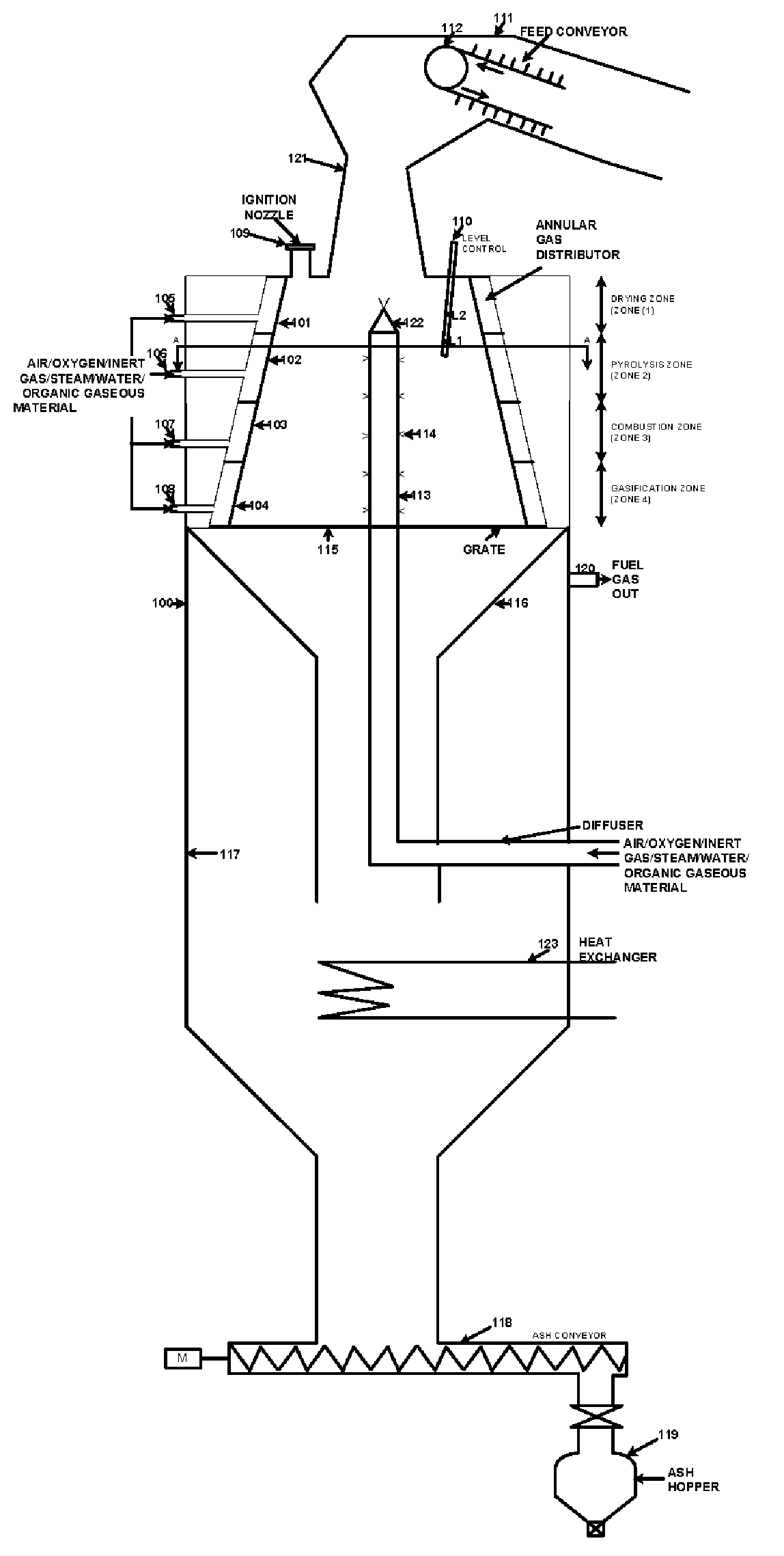
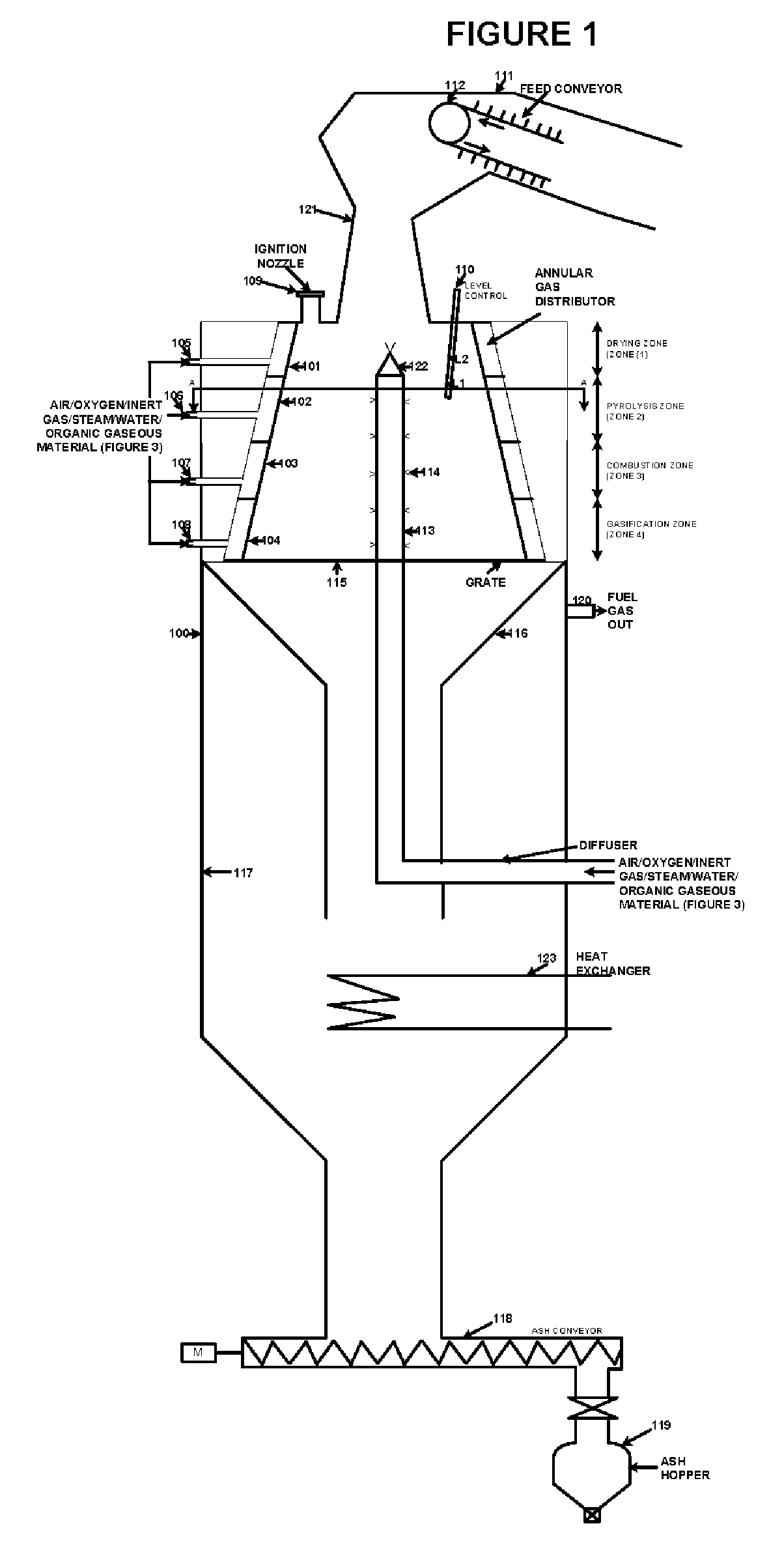
Method and apparatus for generating combustible synthesis gas
a synthesis gas and synthesis method technology, applied in the field of waste to energy systems, can solve the problems of tar in the chimney, unwarranted discharge of polluting compounds, smoke and discharge to the detriment of human health, etc., and achieve the effect of maximizing the conversion of these materials
- Summary
- Abstract
- Description
- Claims
- Application Information
AI Technical Summary
Benefits of technology
Problems solved by technology
Method used
Image

Examples
example 1
[0069] 2,000 lb / hr of food wastes with the analysis shown in Table 1 are fed into the downward draft reactor. The air flow rate is adjusted such that the reactor temperature is at 1800° F. In this example, 3,561 lb / hr of air flow is required.
[0070] The pressure in the reactor is kept slightly above atmospheric. 250 lb / moles / hr of synthesis gas are produced with the composition as follows:
TABLE 2MOLE %PRODUCT GASWETDRYH220.1725.35CO12.4615.66CO27.839.84N2 + Ar39.0949.11H2S0.030.04H2O20.42—TOTAL100.00100.00Gross Heating Value, Btu / SCF105.79132.94Synthesis gas Flow, lbmole / hr250199
example 2
[0071] Same as Example 1, except that an enriched air with 40 mole % of oxygen content is used. 1615 lb / hr of enriched air flow is required to maintain the reactor at 1800° F. 185 lbmoles / hr of synthesis gas are produced with the composition as follows:
TABLE 3MOLE %PRODUCT GASWETDRYH230.1740.00CO18.1724.09CO29.1912.18N2 + Ar17.8623.69H2S0.030.04H2O24.58—TOTAL100.00100.00Gross Heating Value, Btu / SCF156.64207.70Synthesis gas Flow, lbmole / hr185140
example 3
[0072] Same as Example 1, except that an enriched air with 95 mole % of oxygen content is used. Only 663 lb / hr of enriched air flow is required to maintain the reactor at 1800° F. 153 lbmoles / hr of high quality synthesis gas are produced with the following composition:
TABLE 4MOLE %PRODUCT GASWETDRYH238.1552.88CO22.6931.45CO210.2914.26N2 + Ar0.971.35H2S0.040.06H2O27.86—TOTAL100.00100.00Gross Heating Value, Btu / SCF197.17273.32Synthesis gas Flow, lbmole / hr153110
PUM
| Property | Measurement | Unit |
|---|---|---|
| diversion angle | aaaaa | aaaaa |
| temperature | aaaaa | aaaaa |
| temperature | aaaaa | aaaaa |
Abstract
Description
Claims
Application Information