Resin pipe and resin molded component

Inactive Publication Date: 2007-01-18
TOYODA GOSEI CO LTD
View PDF5 Cites 31 Cited by
  • Summary
  • Abstract
  • Description
  • Claims
  • Application Information

AI Technical Summary

Benefits of technology

[0036] The operating effects of the filler pipe 20 and the manufacturing method thereof are as follows:
[0037] (3)-1 Because the filler pipe 20 is provided with a corrugated part 30 wherein peaks 30a and valleys 30b are disposed continuously, the filler pipe 20 can be routed easily through a curved passageway by bending the corrugated part 30. Moreover, as is shown in FIG. 3, the corrugated part 30 uses three different shapes with different depths of the valleys 30b, and when considering the resistance to fuel permeation, this provides both ease of pipe design and ease of fuel flow. In other words, the first corrugated part 31 has a valley 30b wherein the depth b1 is small, at 1.5 mm, making it possible to reduce the resistance in the flow path by having the flow path be smoother. Consequently, this is applied to a location wherein the amount of flow is high, in the vicinity of the inlet of the filler pipe 20 when fueling. On the other hand, the second corrugated part 32 and the third corrugated part 33 have larger values for d2 (2 mm) and d3 (3 mm), which provide superior routability due to the ease of bending, and superior vibration absorbance. As a result, these are applied to locations in the middle of the filler pipe 20, where one wishes to provide ease in routing, and wishes to absorb the shifting of the fuel tank due to vehicular vibrations.
[0038] (3)-2 The barrier layer 20c is formed from a resin material with resistance to fuel permeation that is greater than that of the resin material of the outer layer 20e, and thus can block the escape of fuel vapors flowing within the fuel path, reducing the amount of emission to the outside.
[0039] Furthermore, the barrier layer 20c is structured as described below in order to prevent, as

Problems solved by technology

Because of this, it is necessary in the corrugated part 110 to provide a thickness in the barrier layer 104 that anticipates thinnin

Method used


Image

  • Resin pipe and resin molded component
  • Resin pipe and resin molded component
  • Resin pipe and resin molded component

Examples


Example

(1) Structure of a Fuel Supplying Mechanism 10

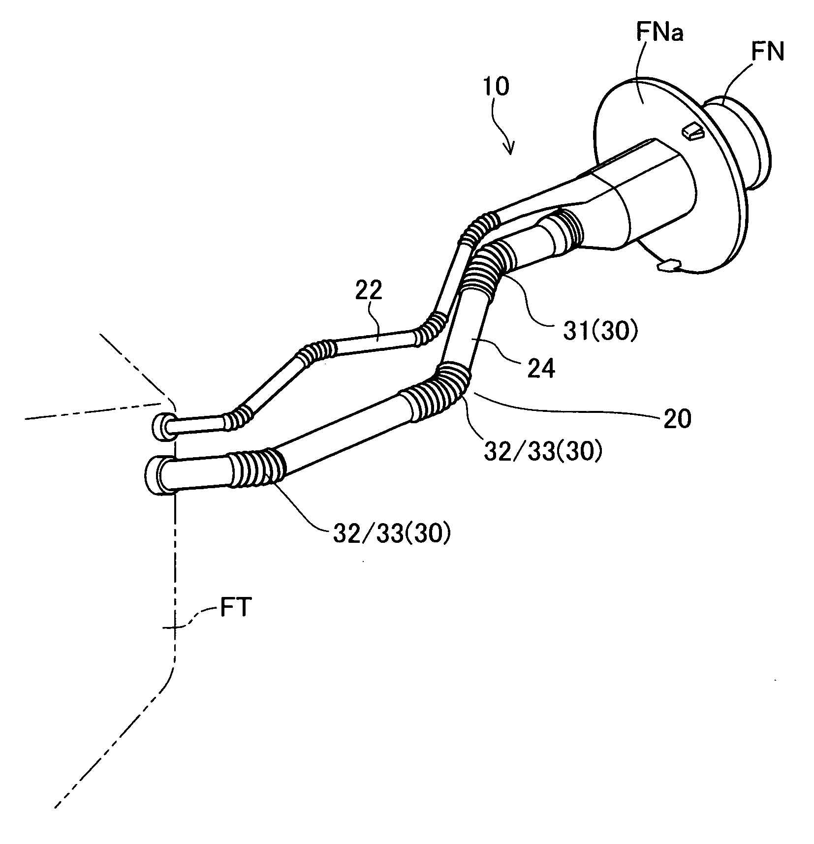
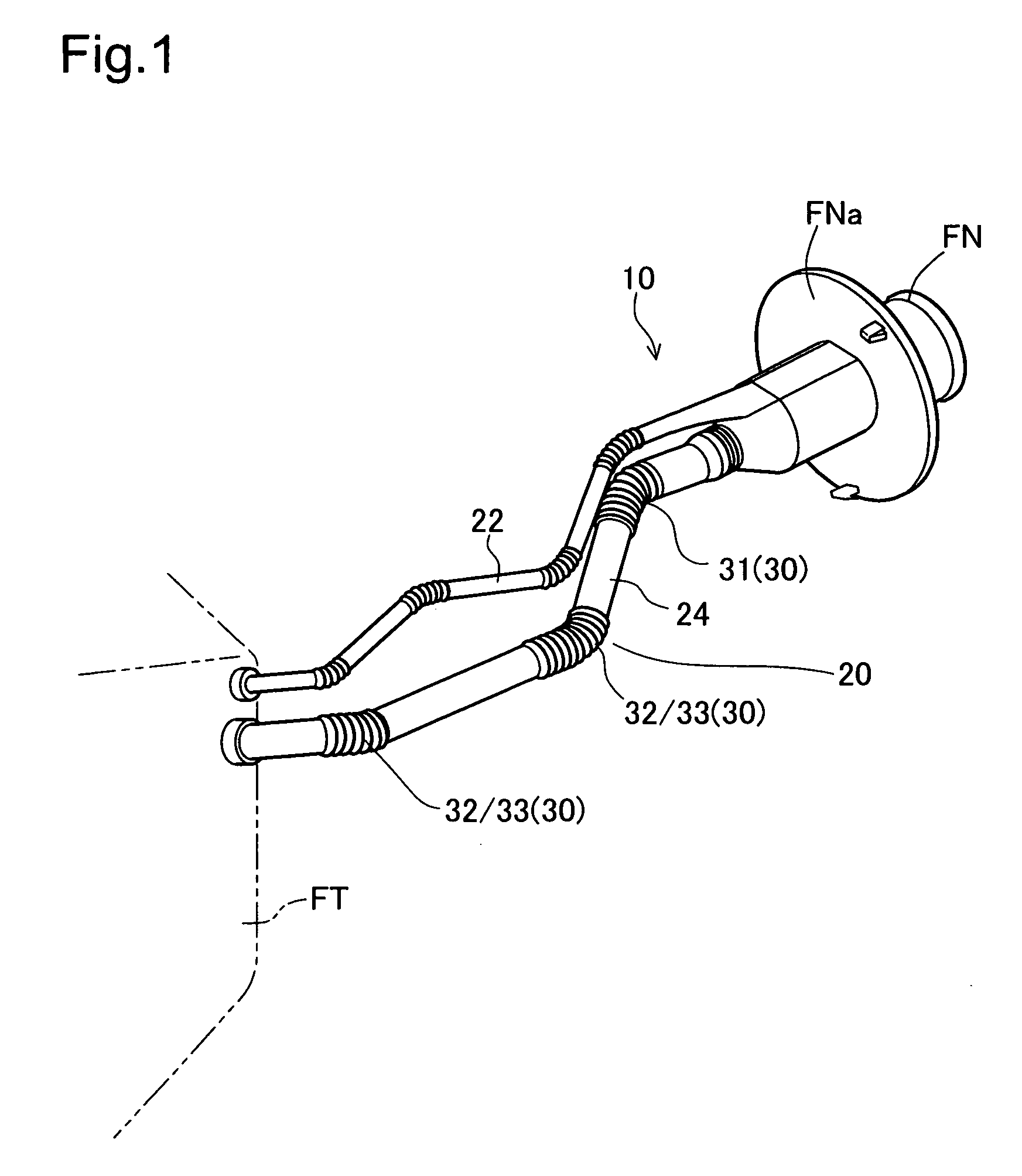
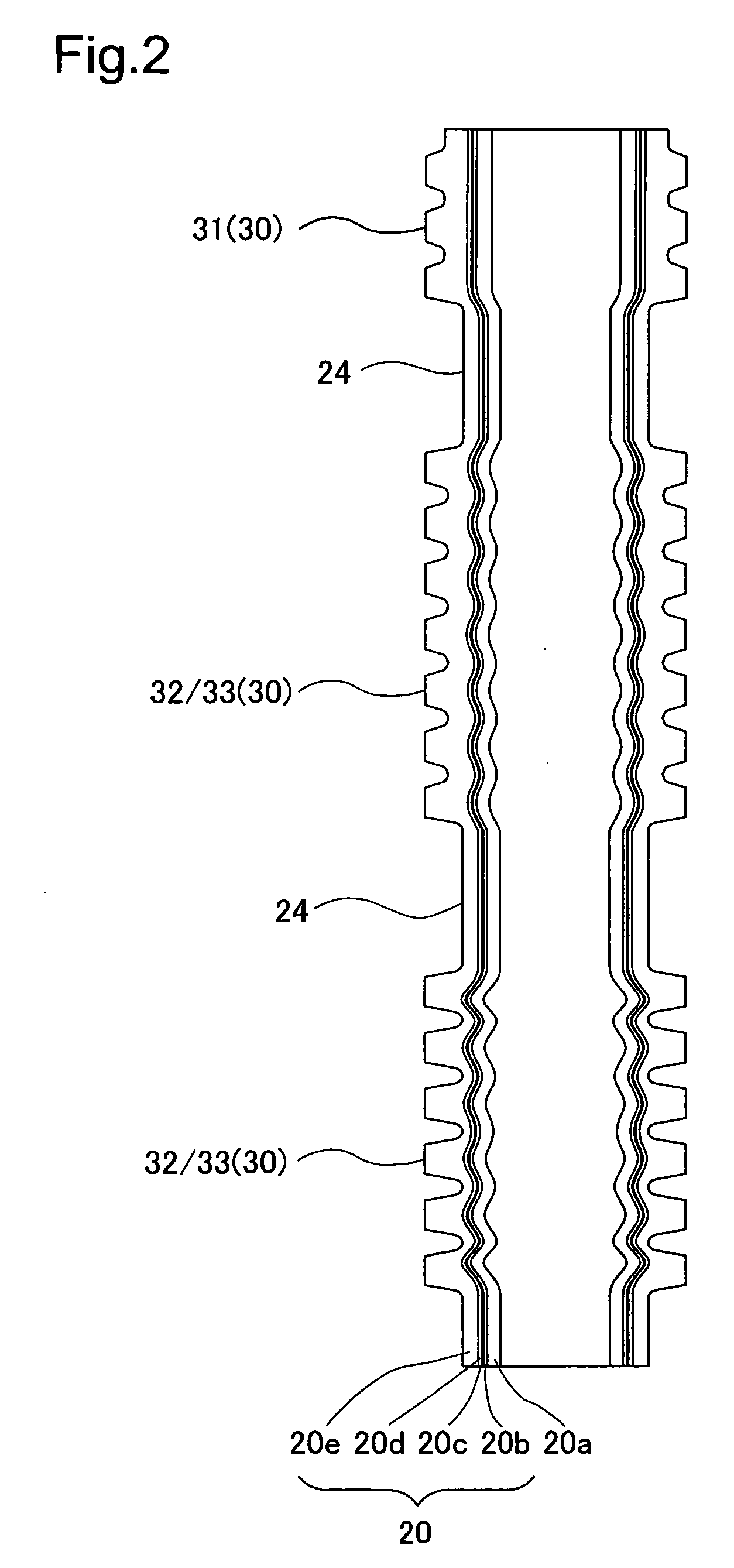
[0027]FIG. 1 is an oblique view illustrating a fuel supplying mechanism for connecting to a fuel tank using a filler pipe having a corrugated part according to a first embodiment according to the present invention. The fuel supplying mechanism 10 is used to supply fuel to an automobile fuel tank FT, and comprises a filler pipe 20 (resin pipe) that is connected to a filler neck FN, and a breather pipe 22 for venting the internal pressure within the fuel tank FT when fuel is filled, where the breather pipe 22 branches from the filler pipe 20. The filler pipe 20 forms a flow path from the filler neck FN to the fuel tank FT. A flange FNa is formed on the outer wall of the filler neck FN, where the fuel supplying mechanism 10 is attached to an automobile member through attaching the flange FNa to an inlet box (not shown). The filler pipe 20 comprises a straight part 24 and a corrugated part 30 that is attached to the straight part 24. The co...


PUM

PropertyMeasurementUnit
Thicknessaaaaaaaaaa
Distanceaaaaaaaaaa
Elasticityaaaaaaaaaa

Abstract

A filler pipe, wherein a flow path for a fluid is formed through multiple resin materials being extruded simultaneously and wherein a corrugated part is shaped through peaks and valleys disposed continuously, comprises an outer layer formed from a high density polyethylene, a barrier layer formed from EVOH with superior resistance to fuel permeation, and an inner layer, formed from high density polyethylene. The structure is such that d<L when the depth from the apex of the peak to the bottom of the valley is defined as d, and the distance from the apex of the peak to the barrier layer is defined as L.

Description

[0001] This application claims the benefit of and priority from Japanese Applications No. 2005-204502 filed Jul. 13, 2005 and No. 2006-138683 filed May 15, 2006, the contents of which are incorporated herein by reference. BACKGROUND OF THE INVENTION [0002] 1. Field of the Invention [0003] The present invention relates to a resin pipe wherein a multilayer pipe, including a barrier layer, is extruded simultaneously and wherein a corrugated part is formed, and to a resin molded component. [0004] 2. Description of the Related Art [0005] Conventionally, when the type of resin pipe has been applied to piping for fuel, such as an inlet pipe, a barrier layer that has excellent resistance to fuel permeation has been interposed in order to reduce the amount of fuel vapor that escapes to the outside. The provision of a corrugated part to facilitate bending along the filling pathway is known in this type of inlet pipe (for example, JP-A-7-217776). FIG. 9 is a cross-sectional view showing the vi...

Claims


Application Information

Patent Timeline
IPC IPC(8): F16L11/00B29C48/32B29C48/92
CPCF16L11/11F16L2011/047B60K2015/03538B29C47/92B60K2015/047B60K2015/0464B60K15/04H02G11/00H02G3/22
Inventor YASUDA, ZENICHINOJIRI, MASANORI
Owner TOYODA GOSEI CO LTD
Why Eureka
Try Eureka