Methods and systems for ultra-precise measurement and control of object motion in six degrees of freedom by projection and measurement of interference fringes

a technology of interference fringes and projections, applied in the direction of instruments, measurement devices, using optical means, etc., can solve the problems of limiting the application of existing devices, impede further innovation, and pre-calibration errors in geometries and dimensions become very significant,

Active Publication Date: 2007-01-18
OHIO STATE INNOVATION FOUND
View PDF5 Cites 23 Cited by
  • Summary
  • Abstract
  • Description
  • Claims
  • Application Information

AI Technical Summary

Benefits of technology

[0012] The present invention is novel method of real-time visual tracking of 6 DOF rigid body motion with near-nanometer precision (±10 nm). The present invention is capable of measuring the following six degrees of freedom: translation along the x, y, and z axes, and rotation about the x, y, and z axes. It is capable of conducting active visual measurement by placing interference fringes on an object, e.g. by reflecting a laser off of the object's surface, and measuring those fringes.

Problems solved by technology

Experts in the field agree that existing devices have limitation barriers that may impede further innovation.
When dealing with dimensions of sub-micrometer range, small pre-calibration errors, such as those resulting from non-orthogonal transducer axes, can lead to erroneous results.
Especially in the case that rotational motion is necessary, the effects of pre-calibration errors in terms of geometries and dimensions become very significant.
Furthermore, in addition to pre-calibration and time variant error sources, a major obstacle in the case of micro-manipulation is the uncertain mechanics of the micro-domain.
However each of these methods requires some sort of mechanical scanning or requires intensive computation which inherently limits its ability to deliver real time information in the z-direction.
Moreover, the achievable depth resolution of all these methods is coupled with the lateral resolution of the image obtained by the optical microscope, which is limited by diffraction.
This ultimately limits the achievable vertical resolution and causes a trade-off between field of view and the vertical resolution of the system.

Method used


Image

  • Methods and systems for ultra-precise measurement and control of object motion in six degrees of freedom by projection and measurement of interference fringes
  • Methods and systems for ultra-precise measurement and control of object motion in six degrees of freedom by projection and measurement of interference fringes
  • Methods and systems for ultra-precise measurement and control of object motion in six degrees of freedom by projection and measurement of interference fringes

Examples


Embodiment Construction

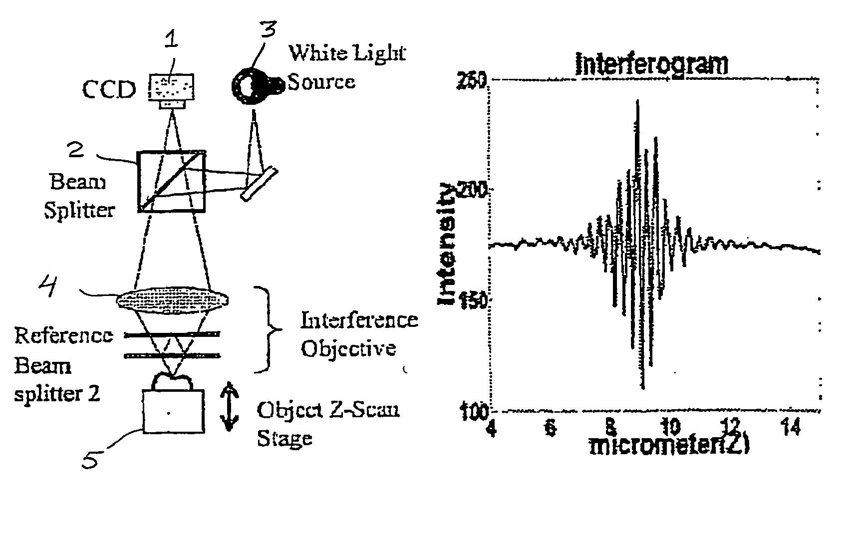
[0027]FIG. 1(A) is a schematic diagram of an SWLI setup which includes a charge-coupled device (CCD) 1, optically coupled with a beam splitter 2 and a light source 3, an interference objective which includes at least one lens 4 and an object stage 5, such as an object Z-scan or magnetic suspension stage.

[0028] The following discussions assume that the object surface being measured is a sufficiently smooth plane surface and that the object is rigid body.

A. Lateral Fringe Pattern Analysis

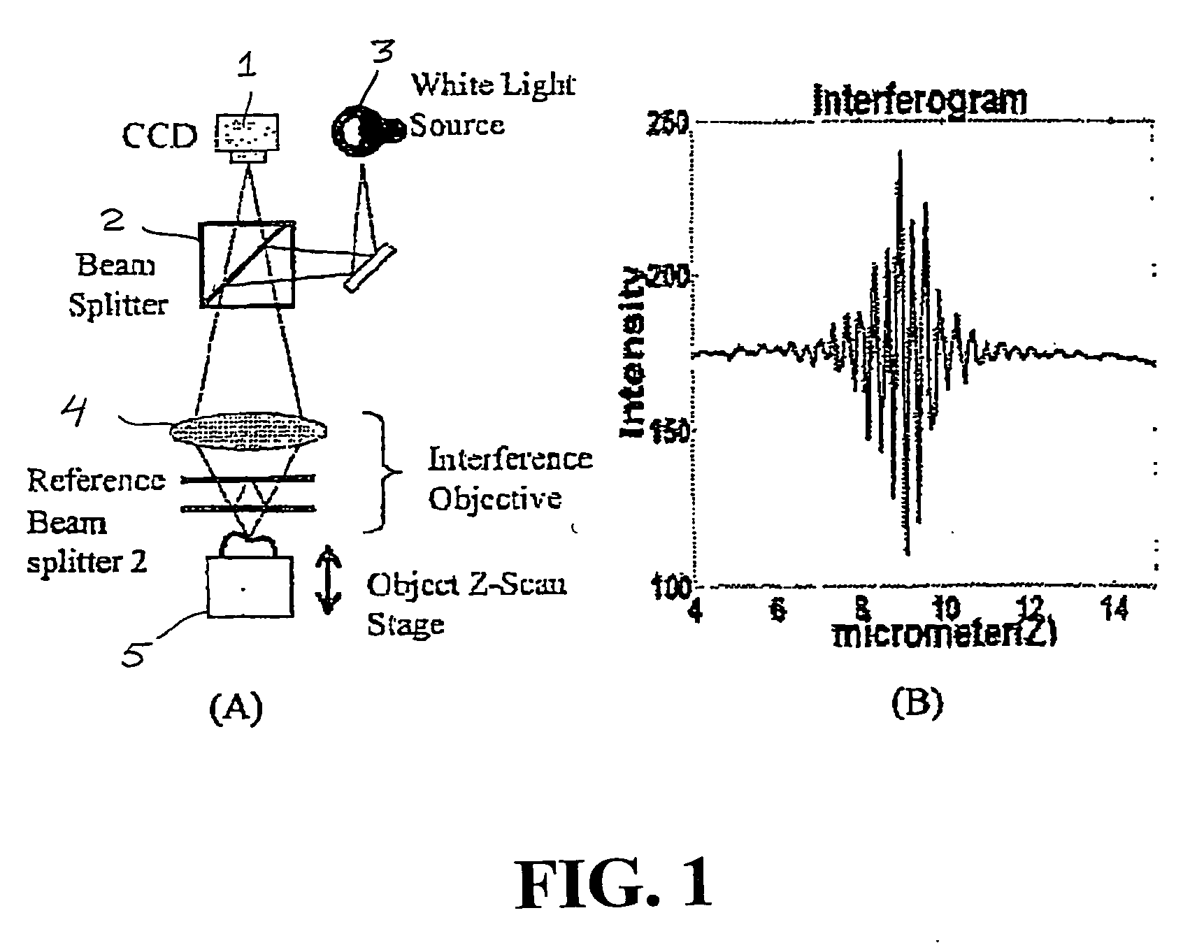
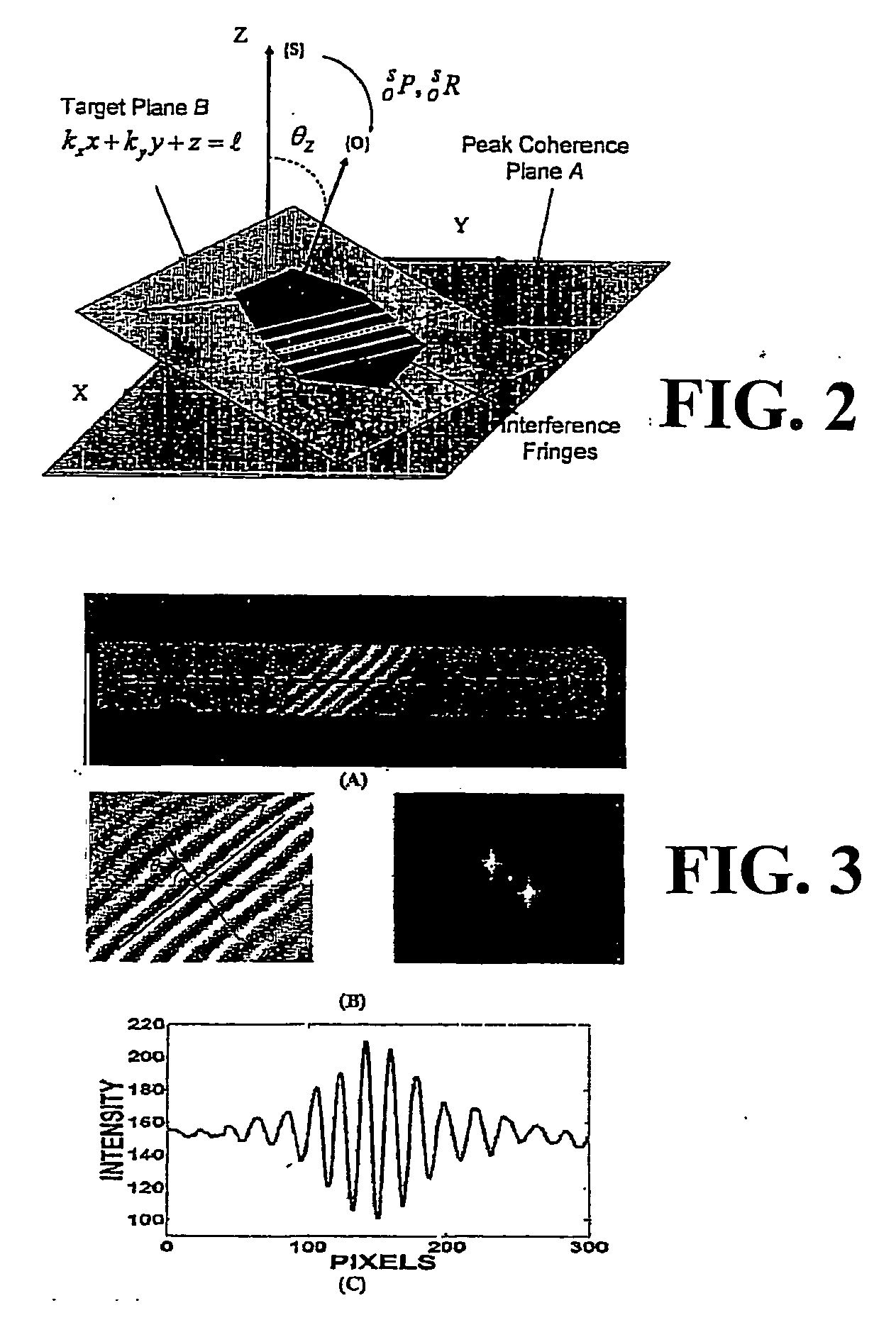
[0029]FIG. 2 shows a spatial model of interference fringes imposed on an object surface under a WLI microscope. The surface of a target object, e.g. shown in FIG. 3-(A), defines the target plane B in FIG. 2. This plane traverses an imaginary plane that is parallel and at equal optical path difference with the reference plane (FIG. 1-(A)) of an interferometer. This imaginary plane is referred to as the peak coherence plane (PCP). Sensor coordinate frame {S} lies on the PCP and acts as the reference...


PUM


Abstract

A system and method for active visual measurement and servo control using laterally sampled white light interferometry (L-SWLI) for real-time visual tracking of six-degree-of-freedom (6 DOF) rigid body motion with near-nanometer precision. The visual tracking system is integrated with a 6 DOF motion stage to realize an ultra precision six-axis visual servo control system. Use of L-SWLI obtains the complete pose of the target object from a single image frame to enable real-time tracking. Six-degree-of-freedom motions are obtained by measuring the fringe pattern on multiple surfaces of the object or from a single surface with additional information gained from conventional image processing techniques.

Description

RELATED APPLICATIONS [0001] This application is a Provisional Conversion of U.S. application Ser. No. 60 / 700,256 filed Jul. 18, 2005.FIELD OF THE INVENTION [0002] The present invention pertains generally to active visual measurement techniques capable of real-time visual tracking of six-degree-of-freedom (6 DOF) rigid body motion with near-nanometer precision (±10 nm). BACKGROUND OF THE INVENTION [0003] The specific approach of using microelectronic fabrication techniques to produce microelectromechanical systems (MEMS) has led to mostly planar parts having dimensions in the vertical direction of only a few micrometers, many other techniques are being developed and applied to make multi-scale 3D devices. Although these methods have yielded primarily experimental devices up until now, many researchers and practitioners believe that multi-scale 3D devices, whose components range in size from several millimeters to micrometers and down to nanometers, will have a much greater applicatio...

Claims


Application Information

Patent Timeline
Patent Type & Authority Applications(United States)
IPC IPC(8): G01B11/02
CPCG01B9/04G01B9/02084G01B9/02067G01B9/0209
Inventor KIM, JUNG H.MENQ, CHIA-HSIANG
Owner OHIO STATE INNOVATION FOUND
Why Eureka
Try Eureka