Holographic viewing device, and holographic viewing card incorporating it
a technology of holographic viewing and holographic image, which is applied in the direction of hologram nature/properties, instruments, printing, etc., can solve the problems of difficult to find various applications, complicated fabrication process, and difficulty in achieving integral formation of transmission holograms with other members, so as to improve aesthetics and decorative attributes, the effect of simplifying construction
- Summary
- Abstract
- Description
- Claims
- Application Information
AI Technical Summary
Benefits of technology
Problems solved by technology
Method used
Image

Examples
first embodiment
A. First Embodiment
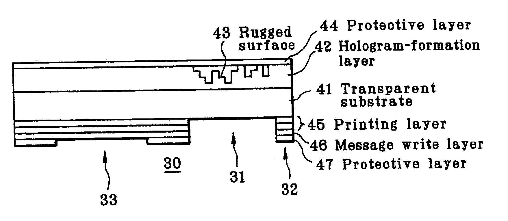
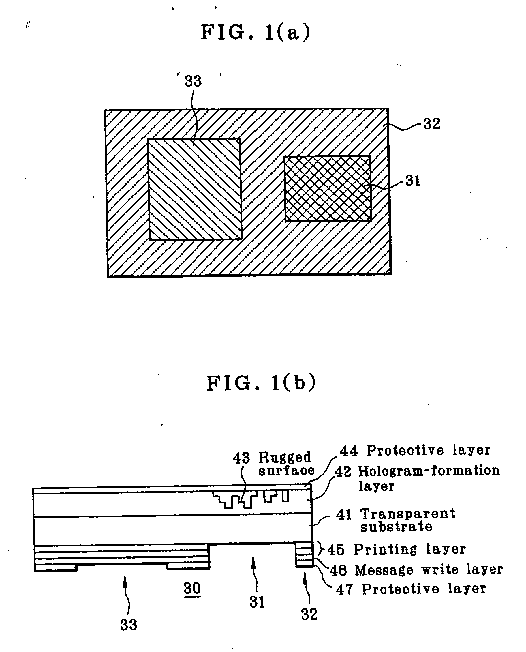
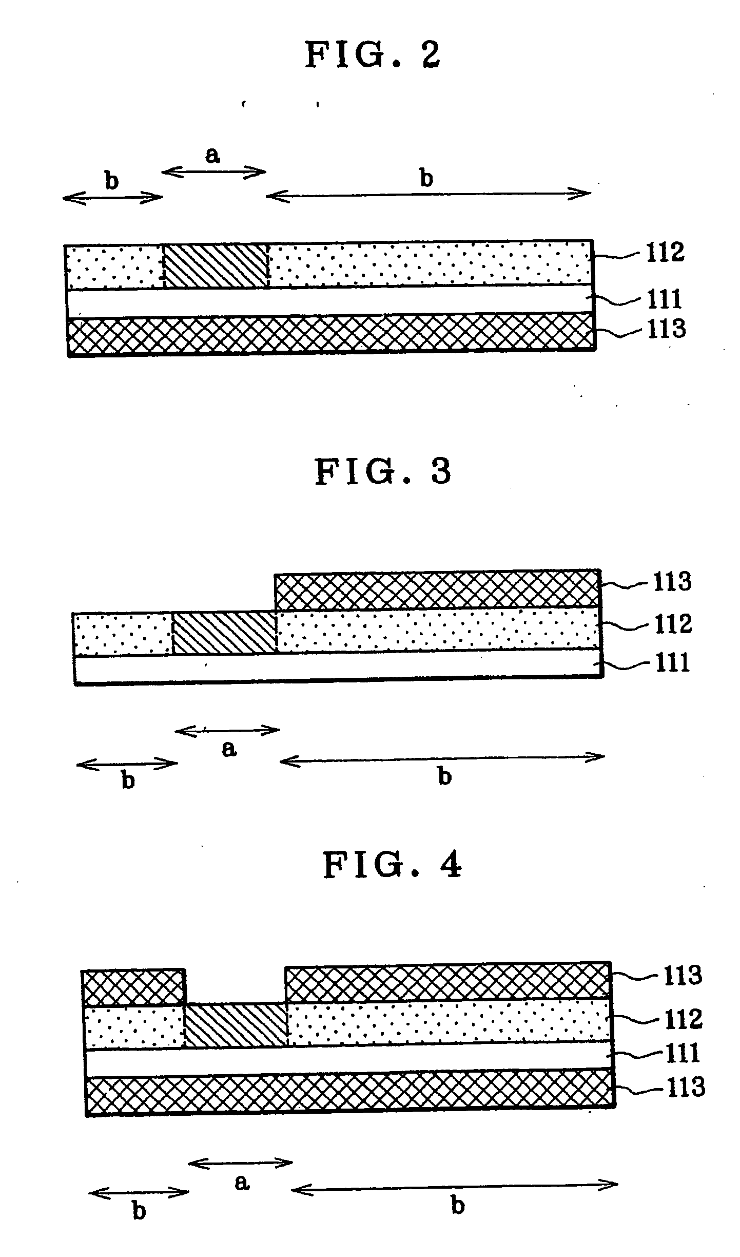
[0079] First, the first embodiment of the holographic viewing card of the invention is explained. The holographic viewing card here comprises a transparent substrate, and an image transform layer formed on said transparent substrate and comprising a transmission Fourier transform hologram area (having a Fourier transform lens function) that enables a given image or message to be viewed near the positions of point light sources upon viewing the point light sources through a hologram and a non-hologram area that is not included in said transmission Fourier transform hologram area and has not the Fourier transform lens function, characterized in that a printable receptor layer is formed on the side of said transparent substrate that faces away from said image transform layer or on said non-hologram area of said image transform layer. As shown typically in FIG. 2, the hologram viewing sheet according to this embodiment comprises a transparent substrate 111, an image t...
second embodiment
B. Second Embodiment
[0166] Next, the second embodiment of the holographic viewing card of the invention is explained. The holographic viewing card of the second embodiment of the invention comprises a transparent substrate, an image transform layer formed on said transparent substrate and comprising a transmission Fourier transform hologram area having a Fourier transform lens function and a non-hologram area that is not included in said transmission Fourier transform hologram area and does not function as a Fourier transform lens, and a protective layer formed on said transmission Fourier transform hologram area of said image transform layer, characterized in that a printable receptor layer is formed on said protective layer.
[0167] As shown typically in FIG. 6, the holographic viewing card here comprises a transparent substrate 111, an image transform layer 112 formed on that transparent substrate 111 and at least comprising a transmission Fourier transform hologram area a and a n...
example
Example 1
Formation of the Image Transform Layer
[0185] A dry etching resist was spin coated on a chromium thin film of a photomask blank plate wherein the chromium thin film of low surface reflection was laminated on a synthetic quartz substrate, using a spinner. For the dry etching resist, ZEP7000 (made by Nippon Zeon Co., Ltd.) was formed at a thickness of 400 nm. An electron beam lithographic system (MEBES 4500 made by ETEC Co., Ltd.) was used with the resist layer to expose a previously computer-generated pattern to light, thereby making the exposed portion of the resist resin readily dissolvable. Afterwards, a developing solution was sprayed onto the readily dissolvable portion (spray development) for its removal, thereby preparing a resist pattern.
[0186] Subsequently, using the formed resist pattern, a non-resist portion of the chromium thin film was etched out by drying etching to expose the quartz substrate. Then, the exposed quartz substrate was etched to form a concave p...
PUM
 Abstract
Description
Claims
Application Information
 - R&D
- Intellectual Property
- Life Sciences
- Materials
- Tech Scout
- Unparalleled Data Quality
- Higher Quality Content
- 60% Fewer Hallucinations
Browse by: Latest US Patents, China's latest patents, Technical Efficacy Thesaurus, Application Domain, Technology Topic, Popular Technical Reports.
© 2025 PatSnap. All rights reserved.Legal|Privacy policy|Modern Slavery Act Transparency Statement|Sitemap|About US| Contact US: help@patsnap.com