Internal thermal management for motor driven machinery

a technology of internal cooling flow and motor drive, which is applied in the direction of magnetic circuit rotating parts, liquid fuel engines, magnetic circuit shape/form/construction, etc., can solve the problems of insufficient airflow through the space, failure of the motor or compressor, and insufficient thermal management of the motor. , to achieve the effect of effective thermal managemen

Inactive Publication Date: 2007-01-25
HAMILTON SUNDSTRAND CORP
View PDF26 Cites 109 Cited by
  • Summary
  • Abstract
  • Description
  • Claims
  • Application Information

AI Technical Summary

Benefits of technology

[0008] This invention addresses internal cooling of motor driven turbo machinery that provi

Problems solved by technology

The combination of higher rotational speeds and smaller size results in significant heat generation, which may reduce magnetization of the rotational rotor and over a prolonged time period may ultimately result in motor

Method used


Image

  • Internal thermal management for motor driven machinery
  • Internal thermal management for motor driven machinery
  • Internal thermal management for motor driven machinery

Examples


Embodiment Construction

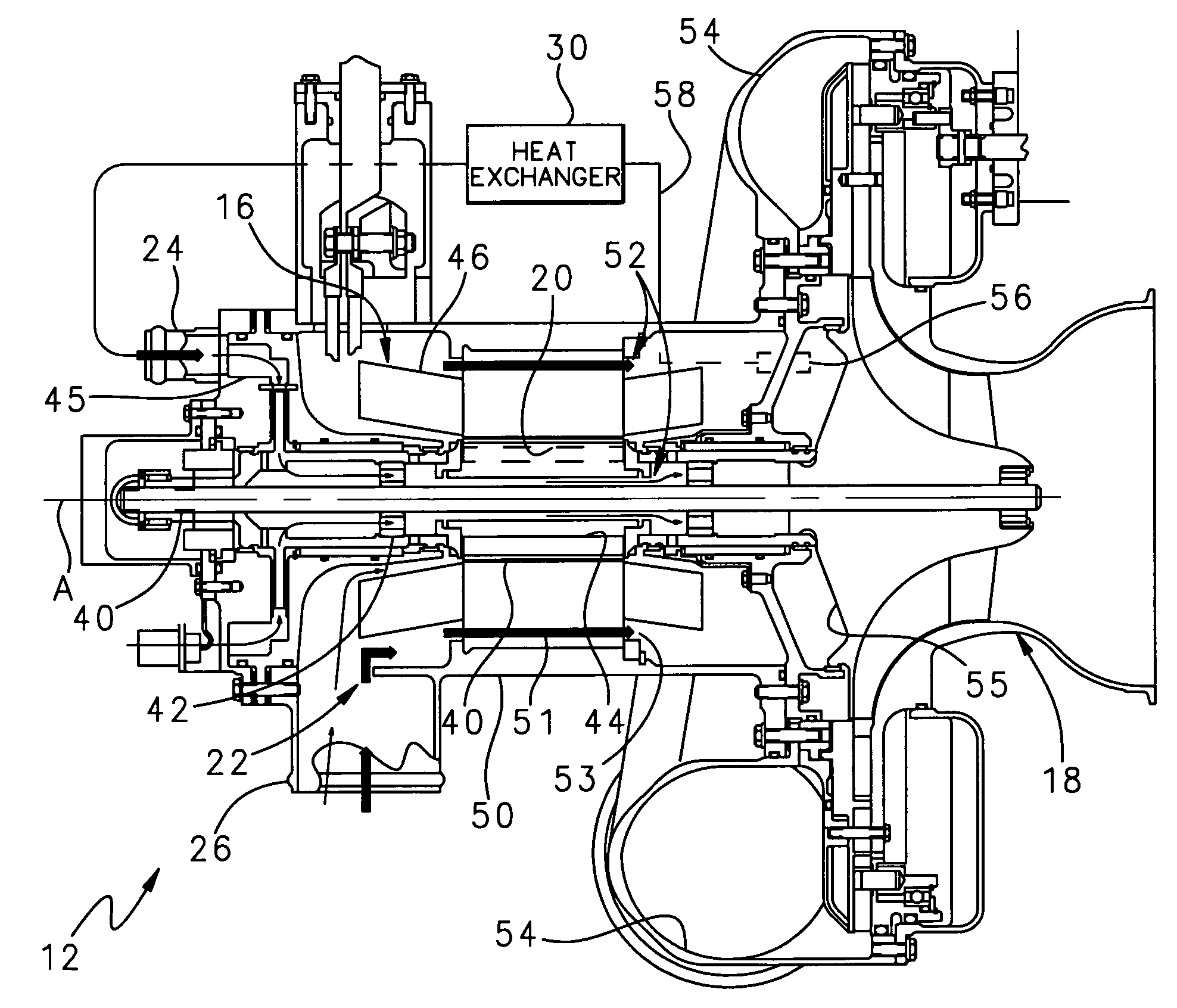
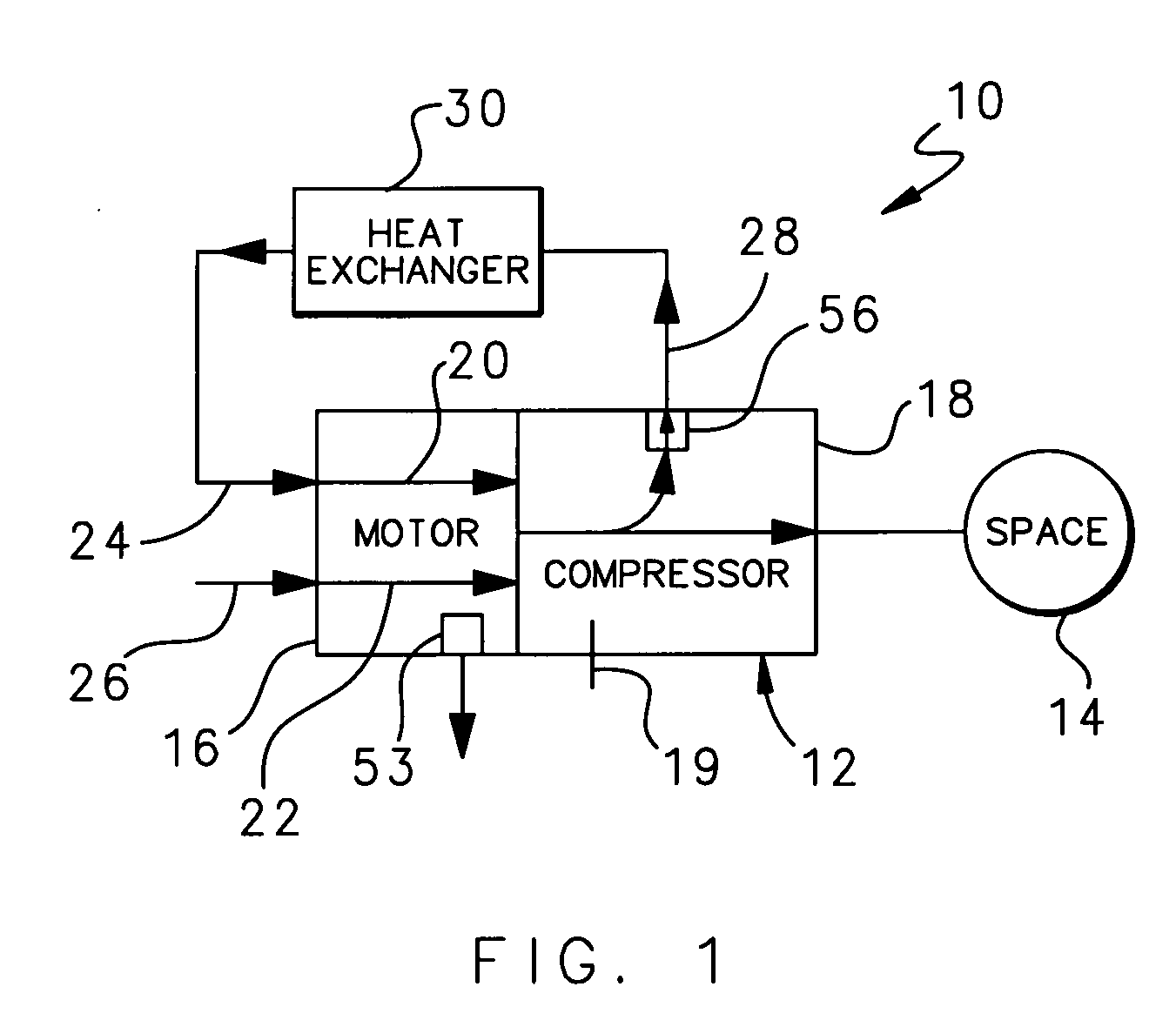
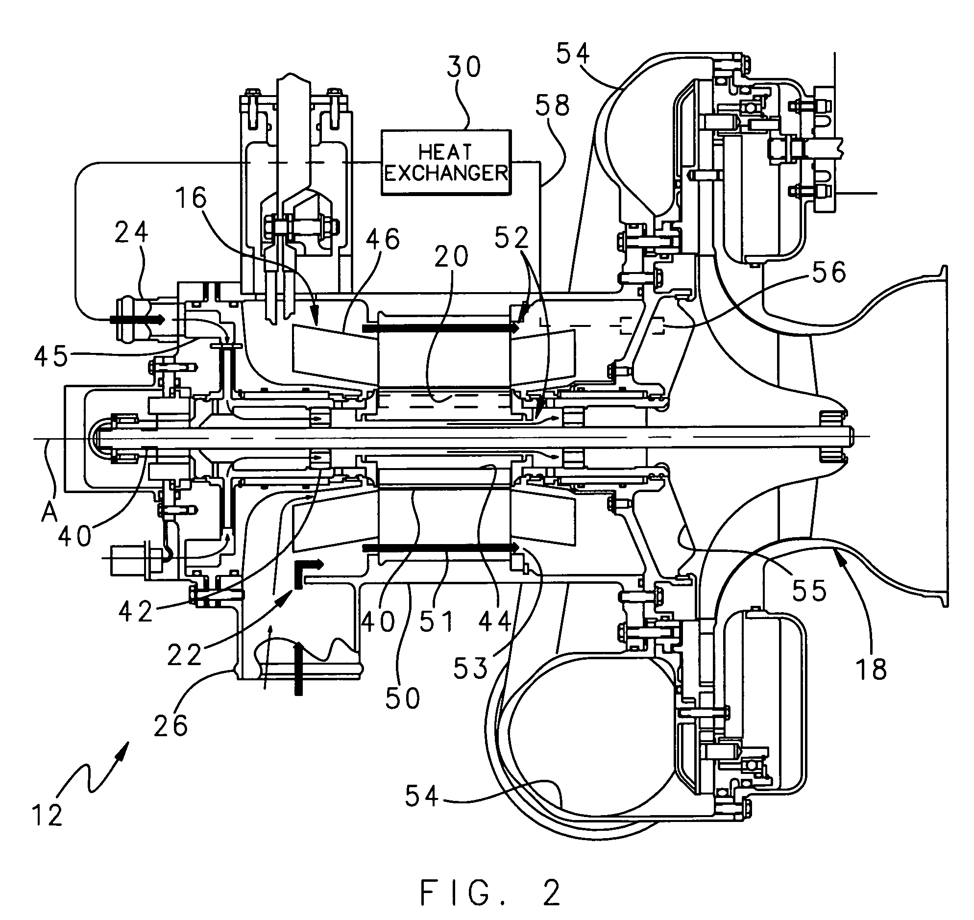
[0020]FIG. 1 schematically illustrates selected portions of a thermal management system 10 that includes a motor driven assembly 12 for supplying pressurized air to a space 14, such as an aircraft cabin. The motor driven assembly 12 includes a motor 16, such as a permanent magnet motor, that drives a compressor 18. The compressor 18 receives air from an outside source through outside source inlet 19 (such as unpressurized ram air or cabin air) and the motor 16, compresses the air, and circulates the compressed air to the space 14.

[0021] The motor 16 includes a first cooling flow passage 20 and a second cooling flow passage 22 that each receive air to provide internal cooling of the motor 16. The first cooling flow passage 20 is connected to a first motor inlet 24 and the second cooling flow passage 22 is connected to a second motor inlet 26. The first cooling flow passage 20 and the second cooling flow passage 22 are each fluidly connected to the compressor 18 and supply air to the...


PUM


Abstract

A motor driven assembly includes a motor having a motor shaft mounted for rotation about a rotational axis and a rotor radially located about the shaft. The motor drives a compressor that receives air from the motor, compresses the air, and circulates the compressed air to a space. The motor includes a first cooling flow passage and a second cooling flow passage that each receive air to provide internal cooling of the motor. A portion of the air compressed in the compressor is diverted from the compressor to a heat exchanger. The heat exchanger cools the compressed air from before the air circulates into the first cooling flow passage to cool the motor. The second cooling flow passage receives air from the environment surrounding the motor driven assembly to further cool the motor.

Description

BACKGROUND OF THE INVENTION [0001] This invention relates to motor driven machinery and, more particularly, to motor driven turbo machinery with an internal cooling flow arrangement. [0002] Typical motors in motor driven turbo assemblies, such as a motor driven compressor for moving air in an aircraft air conditioning system, include a rotational rotor that rotates about a motor shaft and a stator spaced radially outward of the rotational rotor. The design desire for the aircraft industry has been toward motors of smaller physical size, which provide increased power. As a result, progressively smaller motors are being driven at progressively higher rotational speeds. The combination of higher rotational speeds and smaller size results in significant heat generation, which may reduce magnetization of the rotational rotor and over a prolonged time period may ultimately result in motor or compressor failure. [0003] One possible solution to heat generation in the motor is utilizing airf...

Claims


Application Information

Patent Timeline
IPC IPC(8): H02K9/00H02K1/32
CPCF04D25/082F04D29/584F02C7/12H02K9/10H02K9/22H02K7/14F04D25/06F04D29/5806F04D29/053H02K9/227
Inventor PAL, DEBABRATAVANEK, LAURENCE D.SABAN, DANIEL M.
Owner HAMILTON SUNDSTRAND CORP
Why Eureka
Try Eureka