Microwave transmitter and the method for increasing envelope bandwidth

a microwave transmitter and envelope bandwidth technology, applied in the field of microwave transmitters, can solve the problems of insufficient modulation accuracy, easy distortion, and decrease in dynamic operation efficiency, and achieve the effects of reducing dynamic operation efficiency, high linearity, and high efficiency of traditional microwave transmitters

Inactive Publication Date: 2007-01-25
NAT SUN YAT SEN UNIV +1
View PDF25 Cites 57 Cited by
  • Summary
  • Abstract
  • Description
  • Claims
  • Application Information

AI Technical Summary

Benefits of technology

[0020] Further, the microwave transmitter of the present invention replaces the phase-modulated carrier having constant envelope magnitude with the pre-distorted IQ-modulated carrier for input to the RF input terminal of the RF power amplifier, endowing the pre-distorted IQ-modulated carrier with a time-varying characteristic so that the power of the input carrier can be adjusted flexibly and, thereby, the problems with respect to decrease in the efficiency of dynamic operation and leakage of the carrier can be reformed, wherein the IQ-modulated carrier, as having been processed with the pre-distortion technique, is combined with the envelope signal for the RF power amplifier to reconstruct the power-amplified RF modulated carrier without distortion at the RF output terminal.
[

Problems solved by technology

However, the main disadvantages of the EER architecture of transmitter include inadequate modulation accuracy, distortion that easily occurs the envelope signal is processed by the pulse-width modulator,

Method used


Image

  • Microwave transmitter and the method for increasing envelope bandwidth
  • Microwave transmitter and the method for increasing envelope bandwidth
  • Microwave transmitter and the method for increasing envelope bandwidth

Examples


Embodiment Construction

[0035] Although the present invention will be full described by reference to the appended drawings for preferred embodiments of the present invention, it will be understood before the description that those skilled in the art may modify the invention described herein while acquire the function of the present invention. Therefore, it will be understood that the following description is a general disclosure to those skilled in the art and, thus, the structure of the present invention should be applicable to different architectures of microwave transmitter. The application of the present invention should not be only limited to the preferred embodiments in the following description.

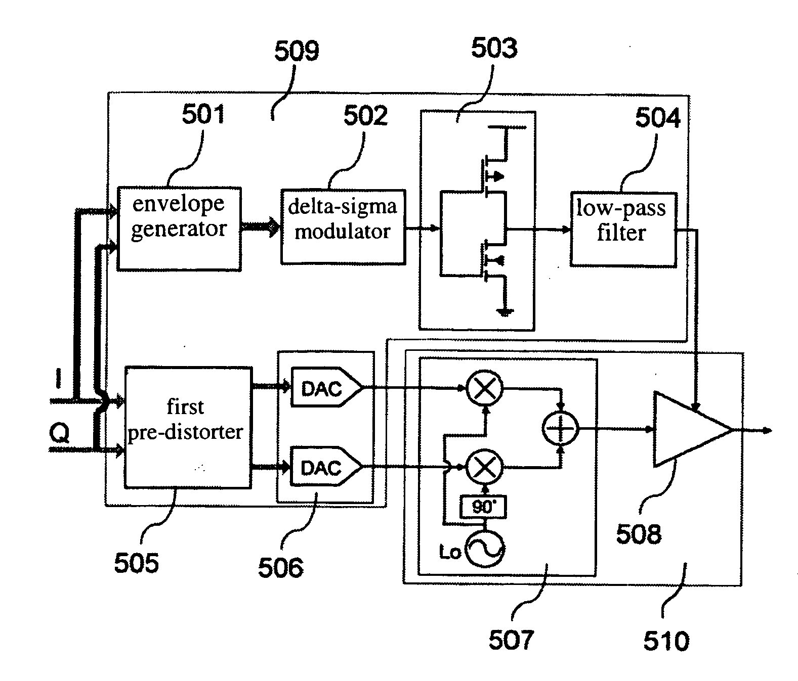
[0036] First, referring to FIG. 5, it shows a block diagram of the architecture of multi-mode microwave transmitter of the present invention. In a preferred embodiment of the present invention, the architecture of transmitter has totally two paths for signal processing, wherein one is for the envelope signal...


PUM


Abstract

The microwave transmitter of the present invention can perform two-terminal dynamic modulation with respect to the voltage supply terminal and the RF input terminal of a RF power amplifier. The microwave transmitter of the present invention comprises a first modulator and a second modulator. The first modulator uses the baseband digital delta-sigma modulation technique to process the envelope signal and outputs this signal to the voltage supply terminal of the RF power amplifier as a supply voltage. The second modulator uses the baseband digital pre-distortion technique to process the IQ-modulated carrier and outputs this signal to the RF input terminal of the RF power amplifier as a RF input signal. Thereby, the RF power amplifier can highly efficiently reconstruct the power-amplified RF modulated carrier without distortion at the RF output terminal. In addition, the baseband digital processing techniques used in the two modulators make the microwave transmitter of the present invention suitable for multi-mode operation.

Description

BACKGROUND OF THE INVENTION [0001] 1. Field of the Invention [0002] The present invention relates to a microwave transmitter and, more specifically, to a microwave and a method thereof applicable to various transmitter specifications for wireless communication systems, to attain the function of multi-mode transmission. [0003] 2. Description of Related Art [0004] In wireless communication handset apparatuses, the major DC (direct-current) power loss results from RF (radio-frequency) power amplifiers. Therefore, one key point of the research on the design of an RF power amplifier always lies in that the RF power amplifier has high linearity without distorting the amplified signal, and has high efficiency to extend the communication time as well. In particular, the digital modulation technique of orthogonal frequency division multiplex (OFDM), which will be widely adopted in the future wireless communication systems, is characterized by significant time-varying envelopes, with a peak-a...

Claims


Application Information

Patent Timeline
IPC IPC(8): H03F3/38
CPCH03F1/0227
Inventor HORNG, TZYY-SHENGCHEN, YUANJAU, JE-KUANLI, JIAN-YULAI, CHANG-MING
Owner NAT SUN YAT SEN UNIV
Why Eureka
Try Eureka