Frequency adjustment techniques in coupled LC tank circuits

a technology of coupled lc tank circuits and frequency adjustment techniques, which is applied in the direction of oscillation generators, generating/distributing signals, electrical apparatuses, etc., can solve the problems of clock network and clock generation in vlsi chips

Active Publication Date: 2007-01-25
INTELLECTUAL VENTURES HOLDING 81 LLC
View PDF18 Cites 56 Cited by
  • Summary
  • Abstract
  • Description
  • Claims
  • Application Information

AI Technical Summary

Problems solved by technology

Clock networks and clock generation in VLSI chips is a critical issue to high performance circuit operation.

Method used


Image

  • Frequency adjustment techniques in coupled LC tank circuits
  • Frequency adjustment techniques in coupled LC tank circuits
  • Frequency adjustment techniques in coupled LC tank circuits

Examples


Embodiment Construction

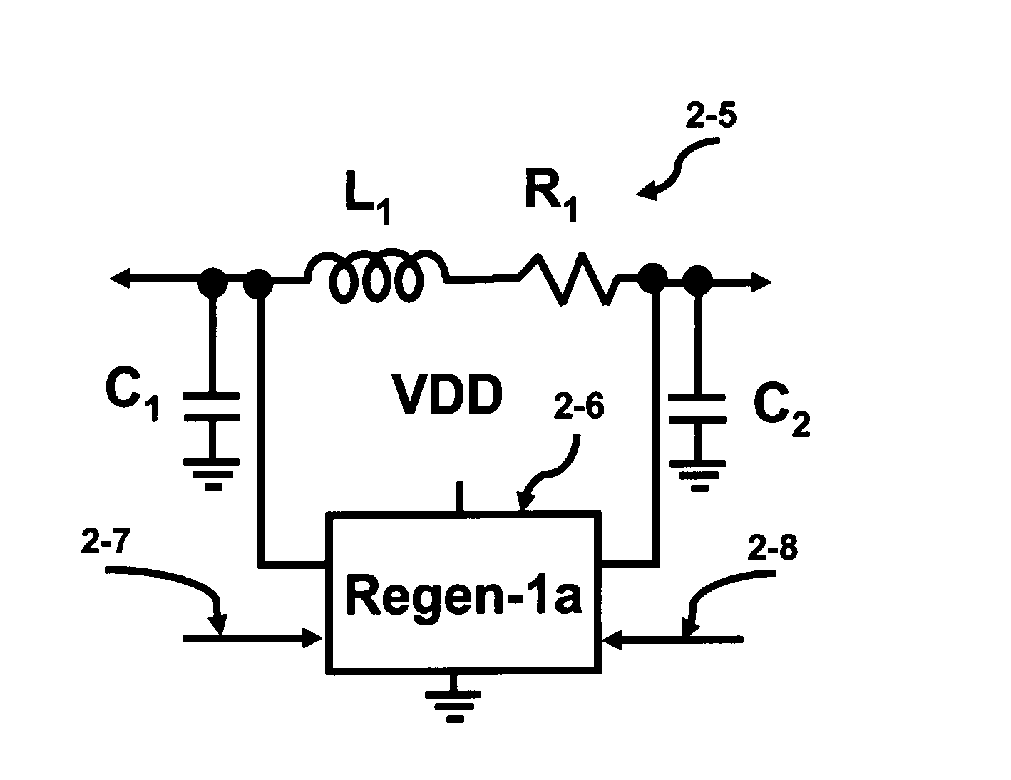
[0107] The LC (inductor-capacitor) tank circuit has been a fundamental building block in many electrical system designs. This circuit is used in wireless, digital, and mixed-signal designs. The basic building elements of the LC tank circuit consist of at least one inductor and and at least one capacitor.

[0108] The invention is based on the discovery that the flux linkage between inductors can be used to synchronize an interwoven network formed from individual LC tank circuits. The flux linkage that occurs between two inductors forms the basis of a structural unit known as a transformer. The coupling coefficient of the transformer can be utilized to lock an interwoven network of tank circuits so they operate in-phase. The ability to phase and frequency lock the interwoven network of tank circuits over the face of the die allows the generation of a unified clock waveform. The additional benefit is that the adiabatic nature of entire interwoven network reduces the power distribution o...


PUM


Abstract

CMOS LC tank circuits and flux linkage between inductors can be used to distribute and propagate clock signals over the surface of a VLSI chip or μprocessor. The tank circuit offers an adiabatic behavior that recycles the energy between the reactive elements and minimizes losses in a conventional sense. Flux linkage can be used to orchestrate a number of seemingly individual and distributed CMOS LC tank circuits to behave as one unit. Several frequency-adjusting techniques are presented which can be used in an distributed clock network environment which includes an array of oscillators. A passive flux linkage, mechanical, and finite state machine technique of frequency adjustment of oscillators are described.

Description

CROSS-REFERENCE TO RELATED APPLICATIONS [0001] The present application is related to the co-filed U.S. applications entitled “MUTUAL INDUCTANCE IN TRANSFORMER BASED TANK CIRCUITRY”, “FABRICATION OF INDUCTORS IN TRANSFORMER BASED TANK CIRCUITRY”, and “FLUX LINKED LC TANK CIRCUITS FORMING DISTRIBUTED CLOCK NETWORKS” filed on Jul. 19, 2005, which are invented by the same inventor as the present application and incorporated herein by reference in their entireties. BACKGROUND OF THE INVENTION [0002] Electronic consumer products are pushing both the bounds of computation complexity and high clocking frequencies. The systems that are experiencing these problems include: VLSI (Very Large Scale Integration), microprocessors, ASIC's (Application Specific Integrated Circuit), SOC (System On a Chip) and FPGA's (Field Programmable Gate Arrays). All of these systems operate at clock frequencies that increase dramatically each year. This higher clock frequency coupled with the increased size of th...

Claims


Application Information

Patent Timeline
Patent Type & Authority Applications(United States)
IPC IPC(8): H03B5/08
CPCG06F1/10H03B27/00H03B5/1243H03B5/1228H03B5/1212H03B2200/0076
Inventor GABARA, THADDEUS JOHN
Owner INTELLECTUAL VENTURES HOLDING 81 LLC
Why Eureka
Try Eureka