Radio tag antenna structure for an optical recording medium and a case for an optical recording medium with a radio tag antenna

a radio tag antenna and optical recording medium technology, applied in the direction of resonant antennas, protective materials radiating elements, instruments, etc., can solve the problems of difficult to illegally remove the resonant tag from the article case to which the resonant tag belongs, the reflective layer or the recording layer is apt to be damaged rather than the reading surface, and the antenna is not always the best way to attach it to the inner peripheral portion of the disk. , to achieve the effect of reducing

Inactive Publication Date: 2007-01-25
KAI MANABU +4
View PDF27 Cites 168 Cited by
  • Summary
  • Abstract
  • Description
  • Claims
  • Application Information

AI Technical Summary

Benefits of technology

[0019] In the light of the above disadvantages, an object of the present invention is to provide a technique which is simple, is small-sized but can secure required reading performance.

Problems solved by technology

An object of this technique is to make it difficult to illegally remove the resonant tag from an article case to which the resonant tag is attached as a sensor.
When a surface (a surface on which a label is attached) on the opposite side to the information reading surface (a surface on which the laser beam is irradiated) is flawed or scratched, the reflective layer or the recording layer is apt to be damaged rather than the reading surface because the protective layer (dielectric layer) on this surface's side is very thin.
However, with respect to an optical recording medium such as a DVD or the like in which a protective layer in almost the same degree as the protective layer on the information reading surface's side is also formed on the label surface's side like a DVD, attaching the antenna to the inner peripheral portion of the disk is not always the best way.
Additionally, a bending work or the like of the antenna, which is not easy, is required because the area of the inner peripheral portion of the disk to which the antenna is attached is limited.
Since a general dipole antenna has an impedance of about 72 Ω, their impedances do not match when the chip and the dipole antenna are connected as they are, which causes a disadvantage that the communicable distance is deteriorated, for example.
This may cause a disadvantage that the communicable distance becomes very short or reading becomes impossible in the worst case when the antenna is connected to an IC chip for a radio tag having high impedance.

Method used


Image

  • Radio tag antenna structure for an optical recording medium and a case for an optical recording medium with a radio tag antenna
  • Radio tag antenna structure for an optical recording medium and a case for an optical recording medium with a radio tag antenna
  • Radio tag antenna structure for an optical recording medium and a case for an optical recording medium with a radio tag antenna

Examples


first embodiment

(A) Description of First Embodiment

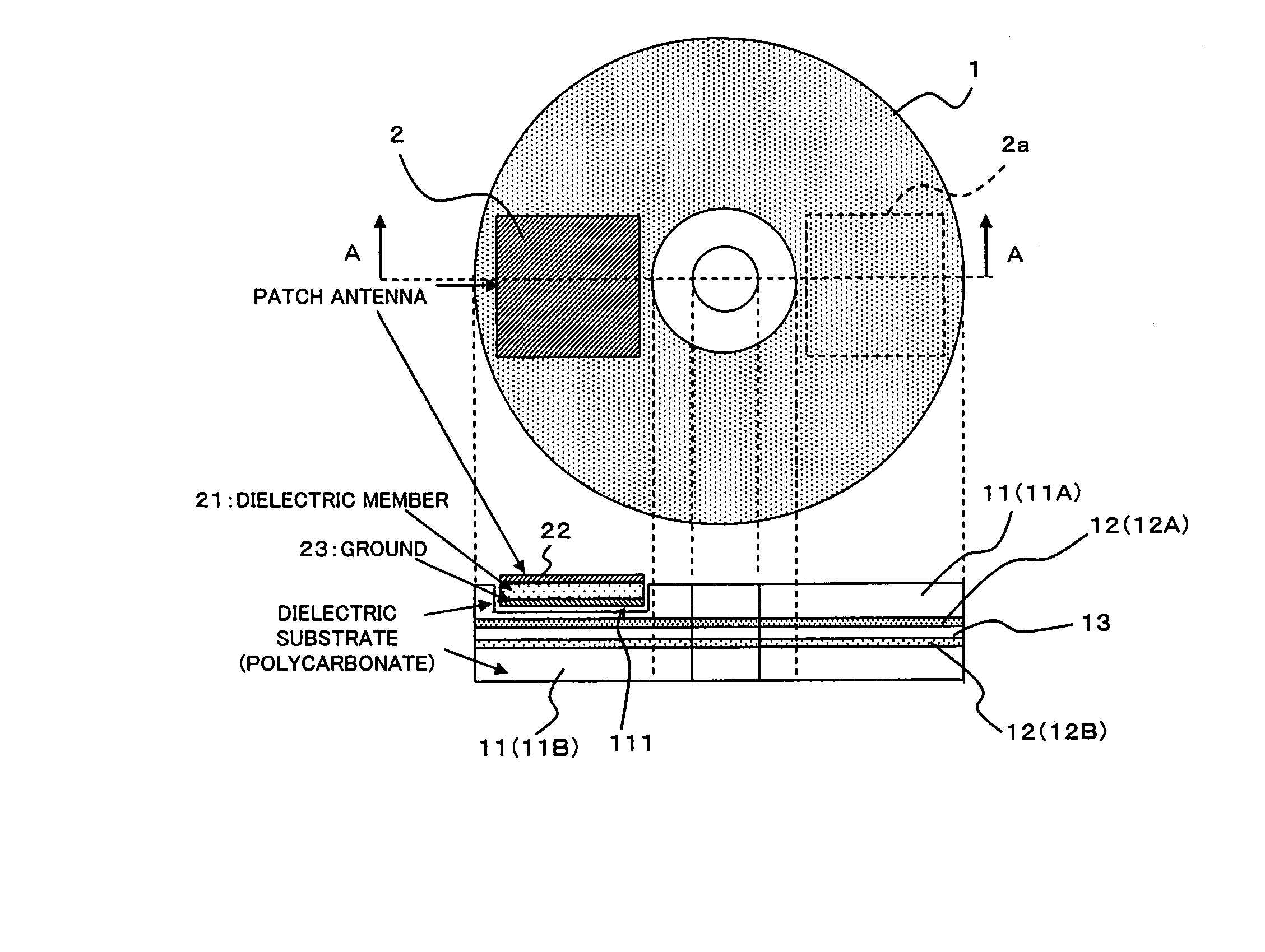
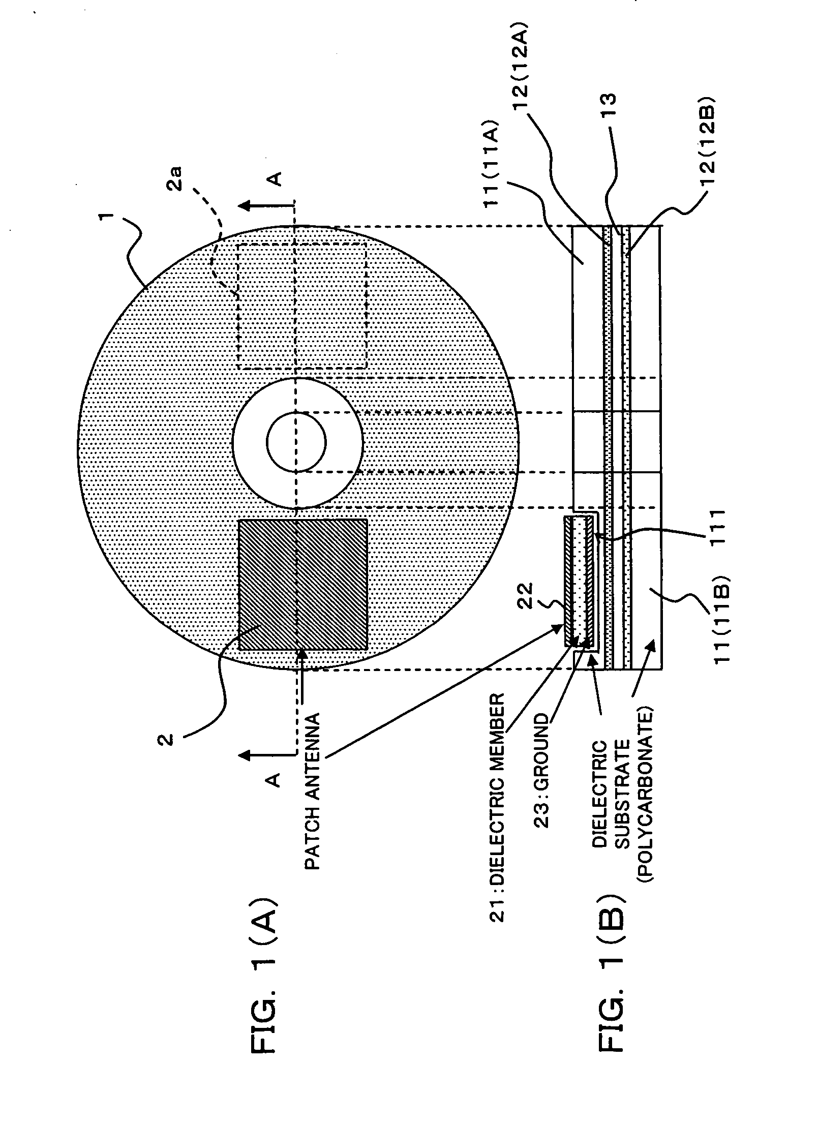
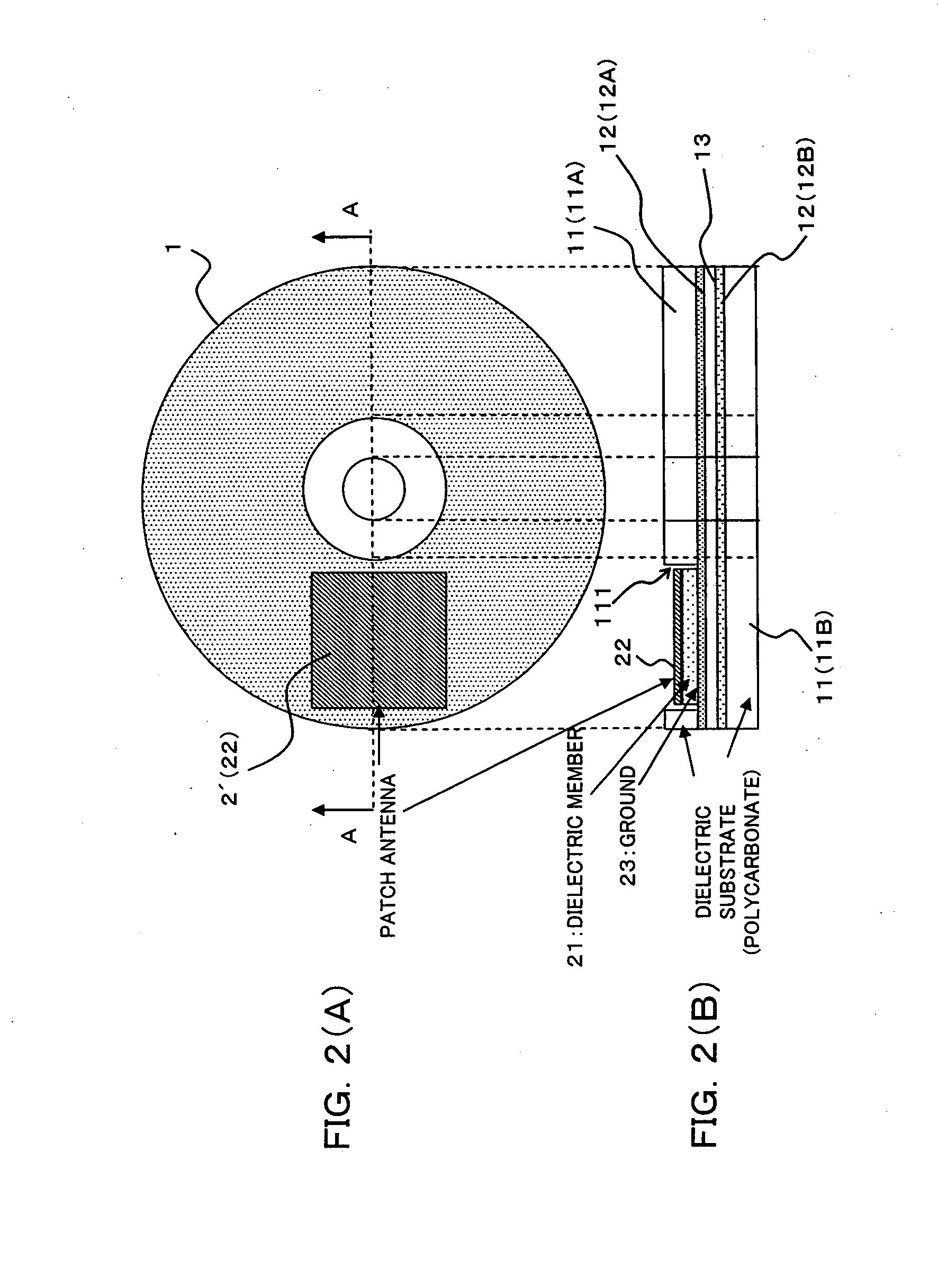
[0063] FIGS. 1(A) and 1(B) are diagrams each showing a radio tag antenna structure for an optical recording medium according to a first embodiment of this invention. FIG. 1(A) is a schematic plan view of a DVD (Digital Versatile Disk) as being an optical recording disk medium, and FIG. 1(B) is a schematic sectional view taken along line A-A of the DVD shown in FIG. 1(A).

[0064] As shown in FIGS. 1(A) and 1(B), the DVD 1 has apparently a similar structure to a CD (Compact Disk). The DVD 1 is generally formed by laminating two disks with an adhesive, each of which has a size according to the standardized specification [for example, an inside diameter of 1.5 cm, an outside diameter of 12 cm (diameter), a thickness of 0.6 mm]. Namely, two disks each of which has a reflective layer (metal layer) 12 (12A, 12B) functioning as a light-reflecting surface formed on one side of a dielectric substrate (dielectric layer) 11 (11A, 11B) are laminated with an adhe...

second embodiment

(B) Description of Second Embodiment

[0098] FIGS. 7(A) and 7(B) are diagrams for illustrating a radio tag antenna structure for an optical recording medium according to a second embodiment of this invention. FIG. 7(A) is a schematic plan view of a CD as being an optical recording disk medium, whereas 7(B) is a schematic sectional view taken along line A-A of the CD shown in FIG. 7(A).

[0099] As shown in FIGS. 7(A) and 7(B), the CD 3 is sized to have an inside diameter of 1.5 cm, an outside diameter (diameter) of 12 cm and a thickness of 0.6 mm. Generally, a reflective layer (metal layer) 12 is formed on one surface of a dielectric substrate (dielectric layer) 11, and a protective layer 14 is further formed thereon, as shown inFIG. 7(B). In FIGS. 7(A) and 7(B), illustration of a recording layer on which information is recorded is omitted.

[0100] In this embodiment, the dielectric substrate 11 also functions as a protective layer for protecting the reflective layer 12 and the recording...


PUM


Abstract

An antenna comprises a dielectric member, an antenna pattern formed on one surface of the dielectric member, and a ground pattern formed on the other surface of the dielectric member. A part or the whole of the antenna is implanted in a dielectric layer on the side from which a laser beam does not come in of an optical recording medium symmetrically having a metal layer reflecting the laser beam and the dielectric layer, thereby to provide a radio tag antenna structure for an optical recording medium which is simple, is small-sized, and can secure necessary reading performance.

Description

CROSS REFERENCE TO RELATED APPLICATIONS [0001] This application is a divisional of U.S. application Ser. No. 10 / 999,690 filed Nov. 30, 2004, now pending, and hereby claims priority to Japanese Application No. 2004-205829 filed on Jul. 13, 2004 in Japan, the contents of which are hereby incorporated by reference.BACKGROUND OF THE INVENTION [0002] (1) Field of the Invention [0003] The present invention relates to a radio tag antenna structure for an optical recording medium, and a case for an optical recording medium with a radio tag antenna. Particularly, the present invention relates to a technique suitable for use to an optical recording disk medium such as a DVD, a CD or the like. [0004] (2) Description of Related Art [0005] Enthusiastically developed is a radio tag system wherein a reader / writer transmits a high-frequency electromagnetic wave, and a radio tag with an IC (Integrated Circuit) chip storing unique information therein receives the high-frequency electromagnetic wave, ...

Claims


Application Information

Patent Timeline
Patent Type & Authority Applications(United States)
IPC IPC(8): H01Q1/38G11B7/24G11B7/24094G11B7/24097
CPCG11B23/0042H01Q1/22H01Q9/0407H01Q1/42H01Q1/38
Inventor KAI, MANABUOISHI, YASUYUKIMANIWA, TORUHAYASHI, HIROYUKIANDRENKO, ANDREY
Owner KAI MANABU
Why Eureka
Try Eureka