Photodetector, diffraction grating, optical pickup and optical disc apparatus

Inactive Publication Date: 2007-01-25
HITACHI MEDIA ELECTORONICS CO LTD
View PDF7 Cites 7 Cited by
  • Summary
  • Abstract
  • Description
  • Claims
  • Application Information

AI Technical Summary

Benefits of technology

[0014] According to the present invention it is possible to provide the photodetector, diffraction grating, optical pickup and optical disc apparatus all capable of effecting stable read or write operation of an optical information recording medium.

Problems solved by technology

Therefore, if there occurs for example tilting of the disc or an axial deviation, the amount of light detected in each photodetector varies greatly, which causes a variation of the tracking error signal and focusing error signal and thus making a stable position control difficult.
Consequently, it may become impossible to effect read and write in a satisfactory manner.

Method used


Image

  • Photodetector, diffraction grating, optical pickup and optical disc apparatus
  • Photodetector, diffraction grating, optical pickup and optical disc apparatus
  • Photodetector, diffraction grating, optical pickup and optical disc apparatus

Examples


first embodiment

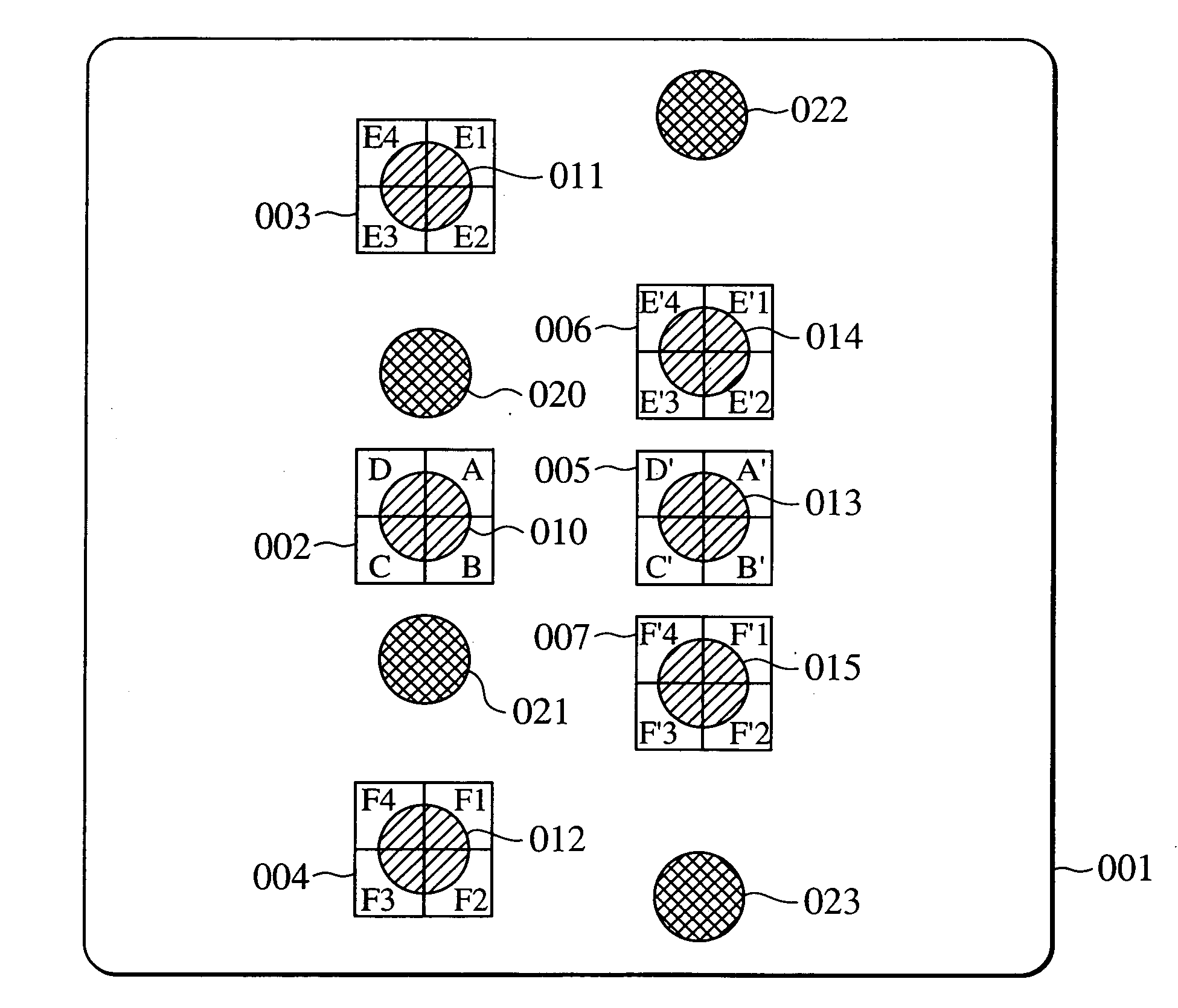
[0037] A first embodiment of the present invention will now be described in detail with reference to FIG. 1. A photodetector according to the first embodiment will here be described.

[0038]FIG. 1 illustrates the photodetector of the first embodiment. In the photodetector, indicated at 001, there are six detection areas 002, 003, 004, 005, 006 and 007. Each detection area is divided in four. More specifically, the detection area 002 has detection surfaces A, B, C, D, the detection area 003 has detection surfaces E1, E2, E3, E4, the detection area 004 has detection surfaces F1, F2, F3, F4, the detection area 005 has detection surfaces A′, B′, C′, D′, the detection area 006 has detection surfaces E′1, E′2, E′3, E′4, and the detection area 007 has detection surfaces F′1, F′2, F′3, F′4.

[0039] The detection areas 002, 003 and 004 receive DVD light beams. More specifically, the detection area 002 receive a DVD main light beam and the detection areas 003 and 004 receive DVD sub-light beams...

second embodiment

[0065] In this second embodiment a description will be given of a two-wavelength multilaser-carrying optical pickup to accommodate an optical disc apparatus capable of writing and reading a DVD and a CD.

[0066]FIG. 3 illustrates the construction of an optical system in an optical pickup 070. A semiconductor laser of a wavelength of about 660 nm is commonly employed to read or write data from or to a DVD type optical disc. A semiconductor laser of a wavelength of about 785 nm is commonly employed to read or write data from or to a CD type optical disc. A two-wavelength multilaser 071 is a laser light source carrying two laser chips thereon which are a DVD laser chip 072 adapted to emit a light beam with a wavelength of about 660 nm for a DVD and a CD laser chip 073 adapted to emit a light beam with a wavelength of about 785 nm for a CD.

[0067] Reference will first be made to the DVD optical system. A DVD light beam is emitted as divergent light from the DVD laser chip 072 which is pr...

third embodiment

[0083] In accordance with a third embodiment a description will be given below of a disturbance light beam which is generated by a diffraction grating with reference to the drawings.

[0084]FIGS. 4A and 4B are schematic diagrams of light beams diffracted by a diffraction grating 060. FIGS. 4A and 4B assume an ideal case. FIG. 4A shows a case where a DVD light beam is incident and FIG. 4B shows a case where a CD light beam is incident.

[0085] For recording to both a DVD and a CD, the diffraction grating 060 is formed with two grating patterns which are a DVD grating pattern 076 and a CD grating pattern 077 since a diffraction grating best suited to generation of a tracking error signal in a DVD is different from that in a CD.

[0086] Reference will first be made to FIG. 4A. When a DVD light beam is incident on the diffraction grating 060, 0-order diffracted light (passing as it is without being diffracted), + first-order diffracted light and − first-order diffracted light are generated...


PUM


Abstract

The present invention provides a photodetector capable of generating highly accurate tracking and focusing error signals free of variations in light quantity caused by interference, in an optical pickup with a two-wavelength multilaser. The photodetector comprises first three light receiving areas arranged linearly to receive three light beams respectively resulting from splitting of a light beam emitted from a laser light source of a first wavelength and second three light receiving areas arranged linearly to receive three light beams respectively resulting from splitting of a light beam emitted from a laser light source of a second wavelength longer than the first wavelength. The distance between both-end light receiving areas out of the first three light receiving areas is longer than the distance between both-end light receiving areas out of the second three light receiving areas.

Description

CLAIM OF PRIORITY [0001] The present application claims priority from Japanese applications Serial No. JP 2005-213606, filed on Jul. 25, 2005 and Serial No. JP 2006-044644, filed on Feb. 22, 2006, the contents of which are hereby incorporated by references into this application. BACKGROUND OF THE INVENTION [0002] The present invention relates to a photodetector for use in read or write of an optical disc, a diffraction grating, an optical pickup, and an optical disc apparatus. [0003] An optical pickup has been heretofore known that carries a two-wavelength multilaser thereon and uses a DPP method for generation of a tracking error signal and an astigmatic method for generation of a focusing error signal. In such an optical pickup, detection area patterns in a photodetector are formed in 3 rows×2 columns and a tracking error signal and a focusing error signal are generated in accordance with signals provided from the detection areas. See, for example, Patent Literature 1 (Japanese Pa...

Claims


Application Information

Patent Timeline
IPC IPC(8): G11B7/00
CPCG11B7/1275G11B2007/0006G11B7/1353G11B7/131
Inventor KAWAMURA, TOMOTOOHNISHI, KUNIKAZUINOUE, MASAYUKIIZUMI, KATSUHIKO
Owner HITACHI MEDIA ELECTORONICS CO LTD
Why Eureka
Try Eureka