

Semiconductor device, circuit and display device using said device and its driving method
Patent Information
- Authority / Receiving Office
- CN · China
- Current Assignee / Owner
- GOLD CHARM LTD
- Publication Date
- 2006-03-22
Smart Images
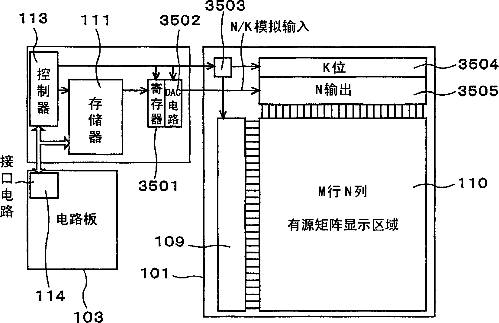
Figure 1 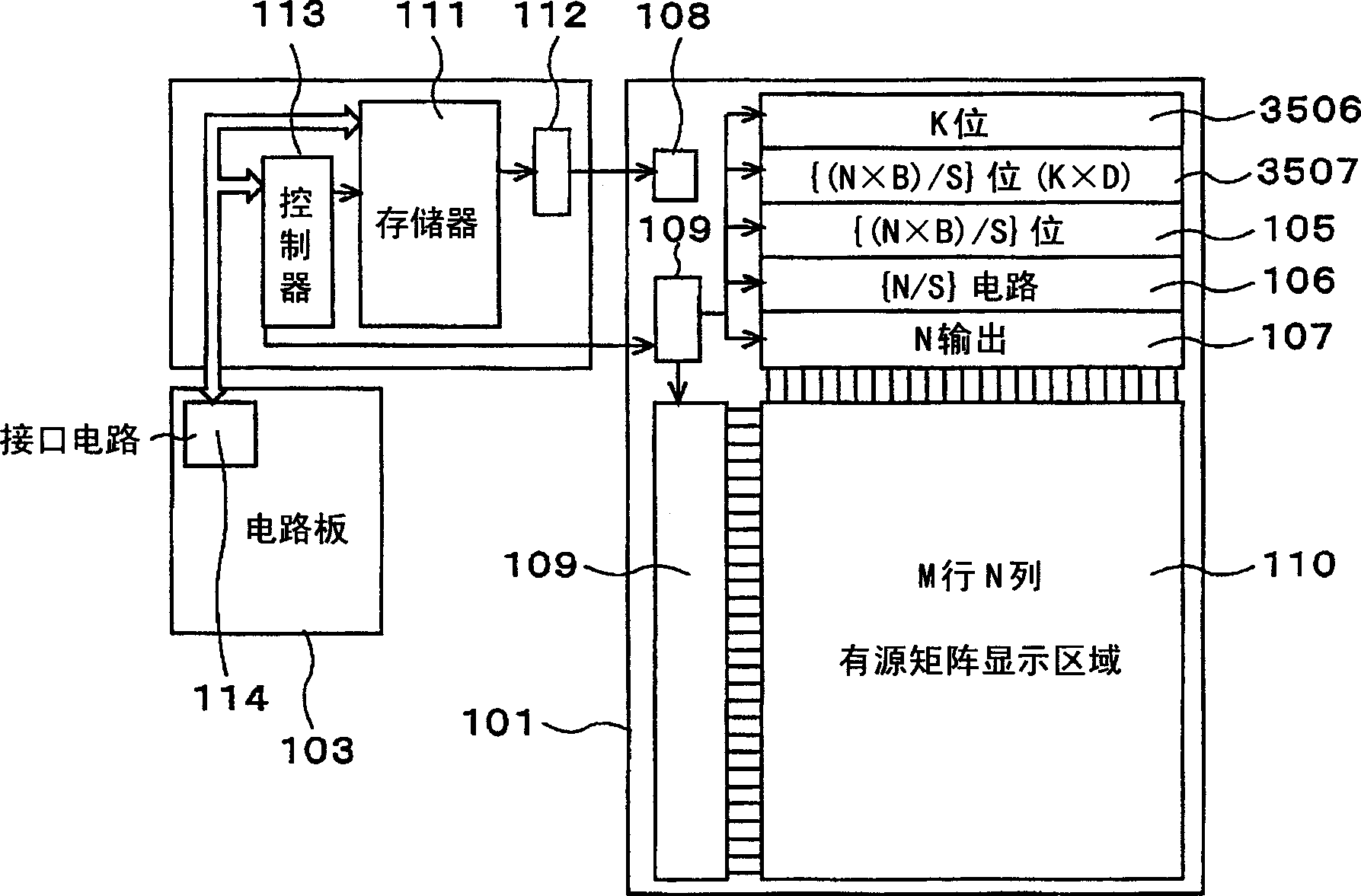
Figure 2 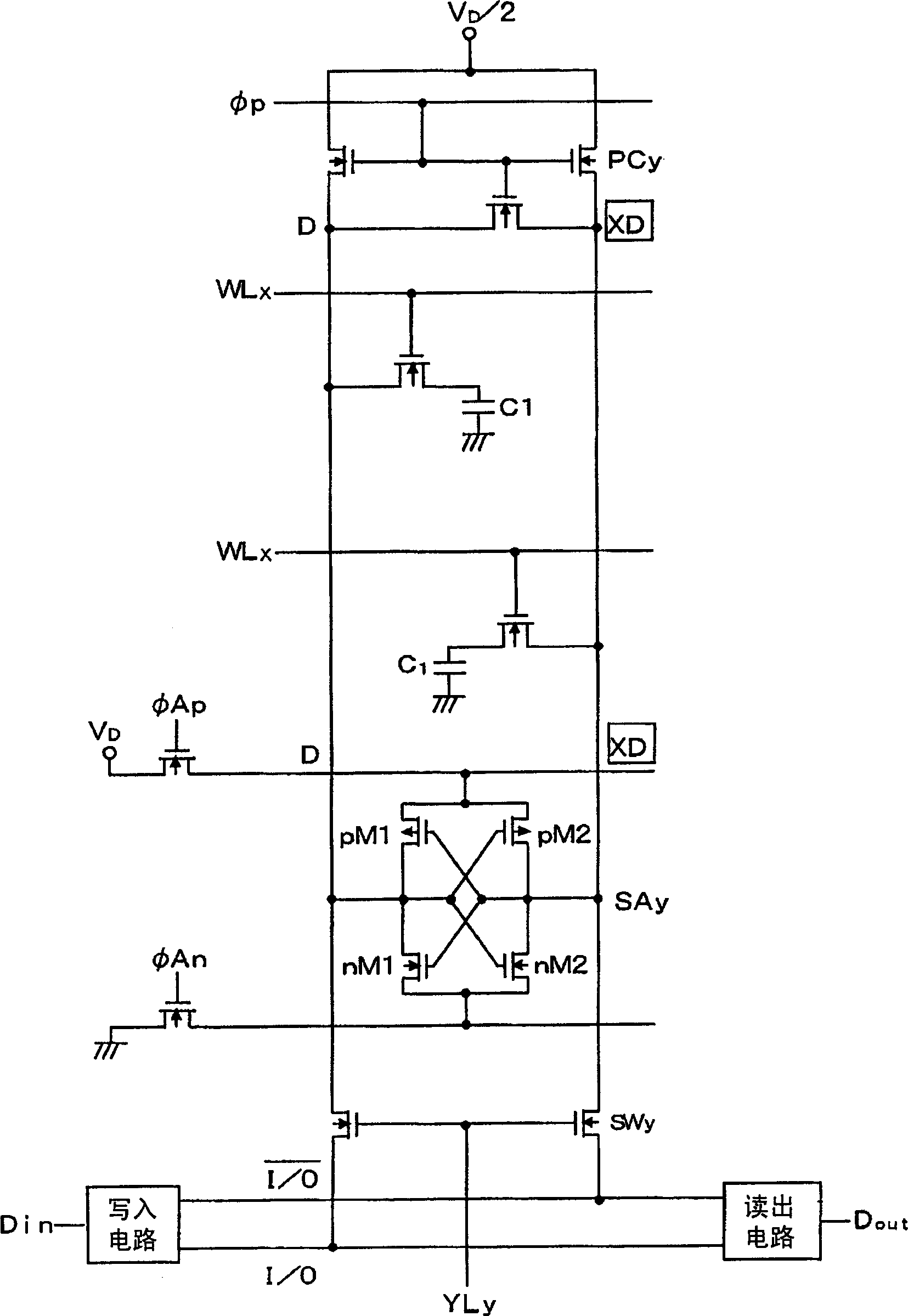
Figure 3
Abstract
Description
technical field
[0001] The present invention relates to a semiconductor device, a circuit and a display device using the semiconductor device, and a driving method of the semiconductor device, more particularly, to a MOS (metal oxide semiconductor) transistors such as polysilicon TFTs (thin film transistors), circuits and display devices using the semiconductor devices, and driving methods of the semiconductor devices. Background technique
[0002] Polysilicon TFTs formed on insulating substrates once required expensive quartz substrates for high-temperature processing, and have been applied to small-sized, high-value-added display panels. Afterwards, a technique was developed in which a precursor film was formed by methods such as low-pressure (LP) CVD, plasma (P) CVD, or sputtering, and then laser annealed to polycrystallize it, which is capable of allowing the use of A technology that forms polysilicon TFTs at relatively low temperatures on glass substrates, etc. At the...