Cell handling device, human tissue regeneration composition, and human tissue regeneration method

a cell and composition technology, applied in the field of regenerative medical treatment, can solve the problems of adversely affecting the cells, difficult to implement cell operations for anyone not in training advanced techniques, and in possession of well-equipped facilities, and achieve the effect of easy injection into the body

Inactive Publication Date: 2007-01-25
JMS CO LTD
View PDF7 Cites 27 Cited by
  • Summary
  • Abstract
  • Description
  • Claims
  • Application Information

AI Technical Summary

Benefits of technology

[0005] The present invention was conceived in the light of the above problems and has the principal objects of enabling harvested or cultured ...

Problems solved by technology

Specifically, since many cells cannot survive or proliferate unless adhering to a scaffold, the cells adhere to the wall of the culture vessel, using it as a scaffold.
To do this, operations including physical detachment and detachment using a chemical agen...

Method used


Image

  • Cell handling device, human tissue regeneration composition, and human tissue regeneration method
  • Cell handling device, human tissue regeneration composition, and human tissue regeneration method
  • Cell handling device, human tissue regeneration composition, and human tissue regeneration method

Examples


first embodiment

[0074] 1-1. Construction of Syringe-Type Cell Handling Device 1

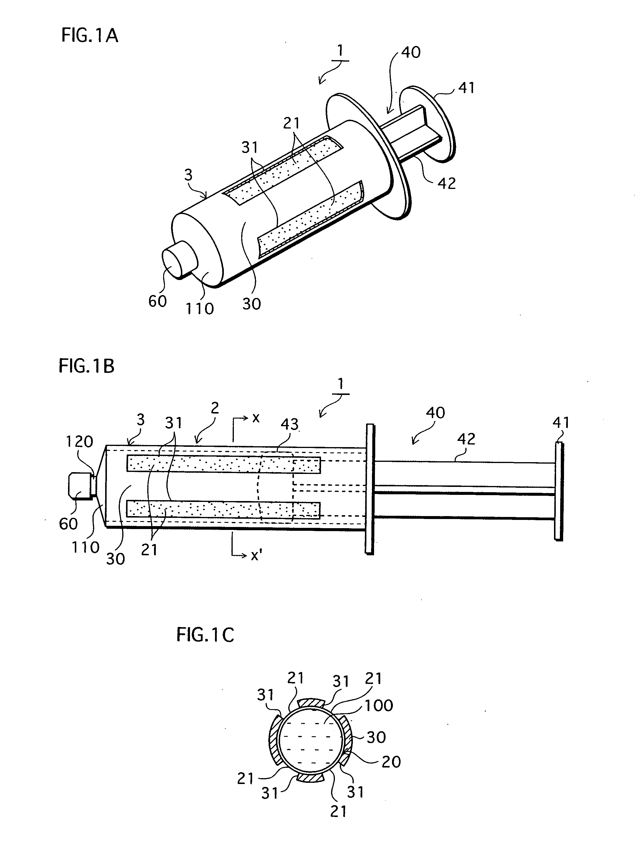
[0075]FIGS. 1A-1C show the structure of syringe-type cell handling device 1 of the First Embodiment that is one example of the cell handling device of the present invention. FIG. 1A is a perspective view, FIG. 1B is a side elevation, and FIG. 1C is a cross-section through X-X′ of FIG. 1B.

[0076] The syringe-type cell handling device 1 shown in FIG. 1 is broadly composed of a syringe main body 2 and a plunger (also referred to as a pressing component or as a piston) 40. A cell suspension 100 is held within the syringe body 2.

[0077] The syringe main body 2 is composed of cylindrical body 3 made by injection molding a material that is non-adhesive with respect to cells to form a cylinder, and a gas permeable film 20 which is described below.

[0078] The cylindrical body 3 is formed with a leur 120 protruding from a disk shaped front section 110 at a front-end surface. Under normal conditions, a cap 60 is fitted to the tip o...

second embodiment

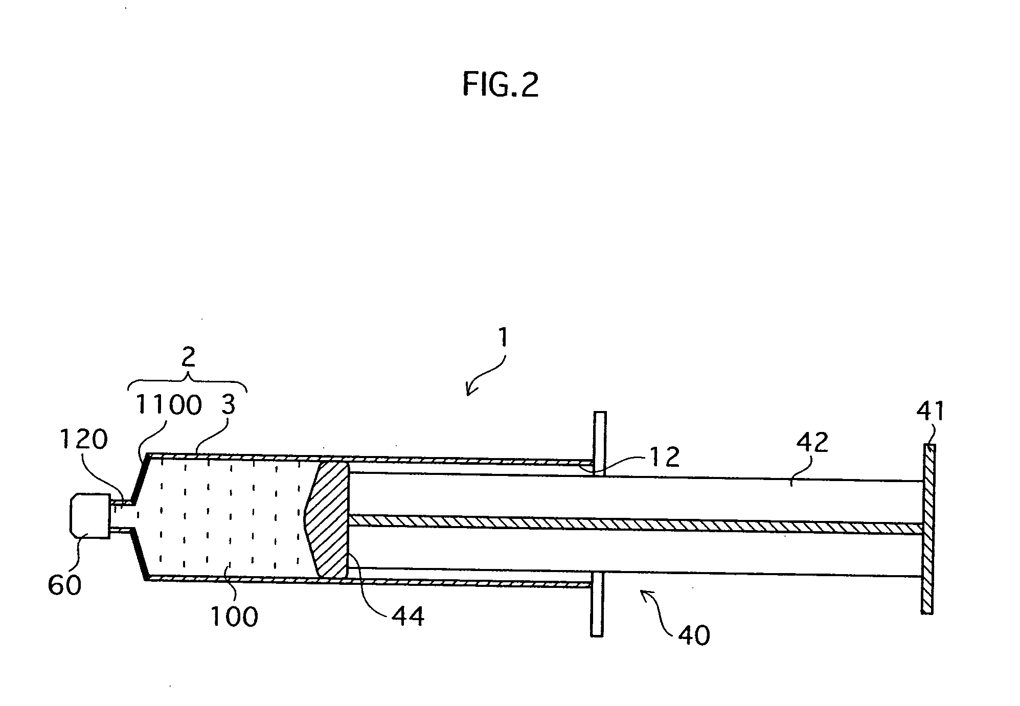
[0114]FIG. 2 is a cross-sectional drawing showing the construction of a syringe-type cell handling device 1 of the Second Embodiment that is an example of a cell handling device of the present invention. The differences from the First Embodiment are that through holes are not provided in the surrounding walls of a cylindrical body 3 in a syringe main body 2, and that a gas permeable region is formed instead in a front section 1100 of the cylindrical body 3. Specifically, this gas permeable region may be formed when forming the syringe main body 2 by using a gas permeable material to make the front section 1100, or by opening through holes in the front section 1100 and fusing or sticking a gas permeable film over the through holes, thereby making the front section 1100 liquid-tight.

[0115] The same type of cell non-adhesive and gas permeable materials as in the First Embodiment can be used. Generally, the tip of a leur 120 has a cap 60 fitted, as shown in FIG. 2, or contains a resin ...

third embodiment

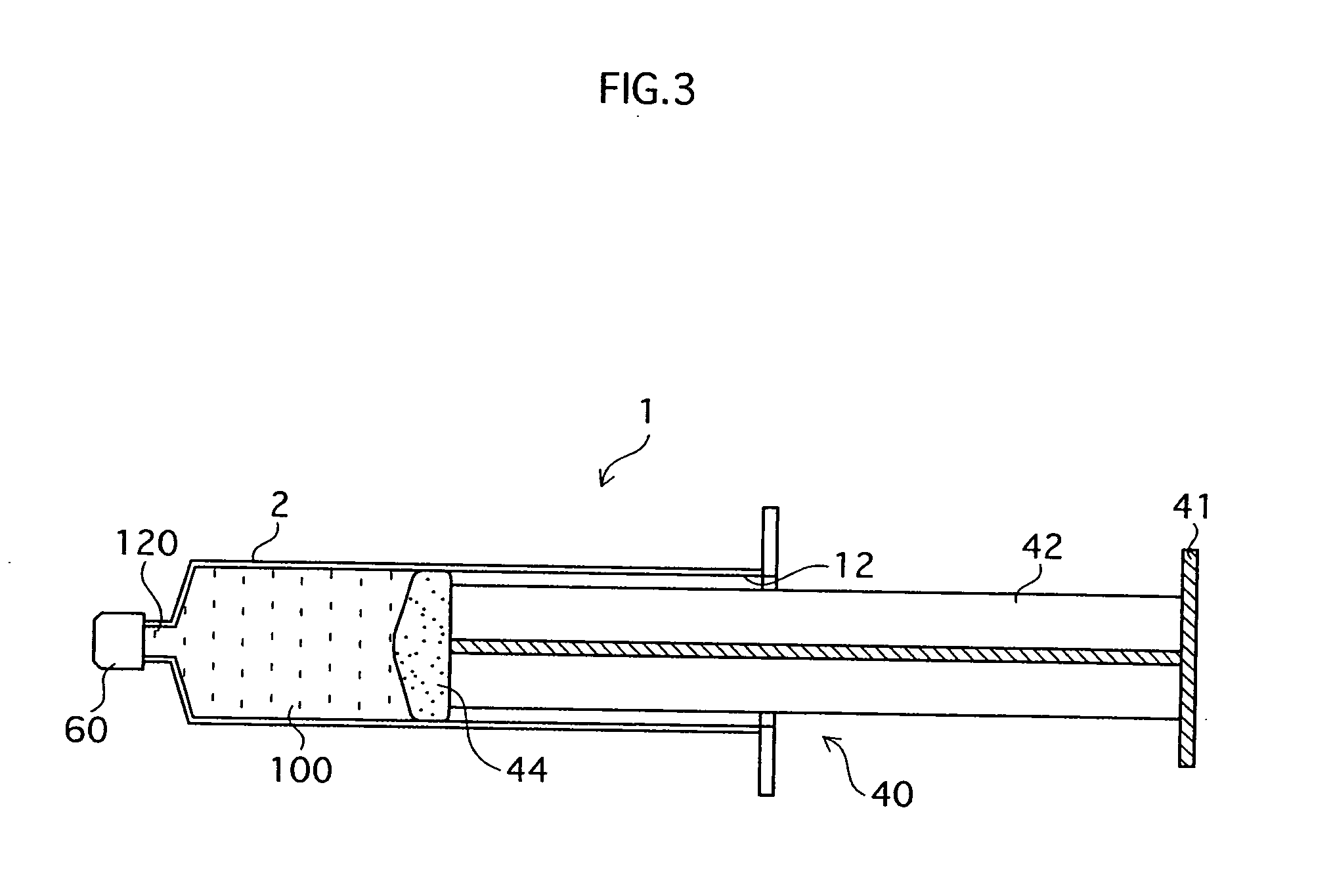
[0121]FIG. 3 is a cross-sectional drawing showing the construction of a syringe-type cell handling device 1 of the Third Embodiment of the cell handling device of the present invention. The differences distinguishing the Third Embodiment from the First and Second Embodiments described above are that the syringe main body 2 is constructed in a cylindrical shape resembling the body of a conventional syringe, and that a plunger head 44 is constructed from a gas permeable material. Any of the materials described in the First and Second Embodiments can be used as the gas permeable material.

[0122] The plunger head 44 is fixed to the syringe-side tip of the body 42 of the plunger 40 and fits tightly against the internal walls of the syringe main body 2 so as to form a liquid-tight seal therewith. Here, as the plunger head 44 is exclusively permeable by gases, cell suspension solution 100 does not leak to the exterior.

[0123] Further, in the Third Embodiment too, constructing both the syri...


PUM


Abstract

The main objects of the present invention, which relates to regenerative medical treatments, are to enable (i) storage and conveyance of harvested or cultured cells without contamination occuring (ii) simple injection of the cells into a living body. To achieve these objects, cells harvested from a living body, or cells obtained by culturing harvested cells, are stored in a syringe-type storage vessel and subsequently transplanted into a living body. It is preferable that at least a part of the storage vessel inner wall in contact with the cells is formed from a cell non-adhesive material. Besides enabling cells in the vessel to take in the oxygen they require to survive, the present invention also enables cells quick and easy transplantation of cells into a living body without a cell detachment process, because cells are prevented from adhering to the inside of the vessel. Further, it is preferable that a stored tissue regeneration composition contains cell culture microcarriers floating in a fluidity medium, and that the cell culture microcarriers are composed of a bioabsorbable material and have cells adhering to their surfaces. Using this kind of tissue regeneration composition, a regenerative treatment can be carried out satisfactorily by simply and quickly transplanting cells from the syringe-type cell storage vessel into a living body without intricate scaffold-related procedures being required.

Description

TECHNICAL FIELD [0001] The present invention relates to regenerative medical treatment, and, in particular, to a cell handling device and a composition used in regenerative medical treatment. BACKGROUND ART [0002] In recent years, on account of the progress in molecular cell biology and cell technology, research into regenerative medical treatment in which differentiated cells or self-renewing and multipotent cells (stem cells) from a living body are transplanted into a patient has continued to advance. Regenerative treatment is a method of treatment in which targeted tissue (including organ) is repaired and caused to recover by transplanting differentiated cells or stem cells into an area where tissue has been lost or into a part of the body responsible for causing disease. Generally, in regenerative medical treatments, extracted cells are cultured independently, or using scaffolds, for a short time in a vessel designed for the purpose. The differentiated or yet to be differentiate...

Claims


Application Information

Patent Timeline
IPC IPC(8): C12M3/00C12N1/21C12N5/06A61K35/12A61L27/00A61L27/38A61L27/56A61L27/58A61M5/28A61M5/31A61P1/00A61P1/16A61P7/00A61P9/00A61P17/02A61P17/14A61P19/02A61P21/04A61P25/16A61P29/00A61P35/02C12M1/26C12M1/36C12M3/02G01N33/48
CPCA61K35/12A61M5/286C12M33/04C12M25/16A61M5/3129A61P1/00A61P1/16A61P17/02A61P17/14A61P19/02A61P21/04A61P25/16A61P29/00A61P3/10A61P35/02A61P7/00A61P9/00A61P9/10C12M1/26G01N33/48C12N5/06
Inventor YUGE, RUIMATSUURA, YOJISAJIKI, TOSHINOBU
Owner JMS CO LTD
Why Eureka
Try Eureka