Device for surgical repair, closure, and reconstruction

a technology of surgical repair and closure, applied in the field of surgical fasteners and techniques, can solve the problems of increasing the susceptibility of the wound to infection, increasing the skin tear around the stitch, and increasing the scarring along the suture path, so as to facilitate more demanding procedures, save time, and increase the effect of skin incisions

Inactive Publication Date: 2007-01-25
SURGICAL SECURITY
View PDF14 Cites 405 Cited by
  • Summary
  • Abstract
  • Description
  • Claims
  • Application Information

AI Technical Summary

Benefits of technology

[0024] The invention can also be used in most settings and locales from acute and field conditions to chronic conditions treated in care facilities. For example, the invention can be used for closure of small laparoscopy ports, which is difficult, particularly in obese patients. In these conditions, standard suturing through a small skin incision is very difficult and takes significant time or requires a larger skin incision to be made. Thus, the invention can make more demanding procedures easier and allow time-consuming procedures to be performed in more urgent situations.
[0025] The invention also allows greater blood flow to the healing tissue. When a conventional stitch is used under high

Problems solved by technology

This results in a tendency of the skin to tear around the stitch.
Second, the skin may pouch out or sacculate between the stitches, greatly increasing the susceptibility of the wound to infection.
Third, because the two sides of the wound are not evenly juxtaposed, scarring along the path of the sutures is increased.
This process is time consuming and requires workspace allowing dexterous manipulation.
While the devices described by Hasson and Yoon are directed to sutureless methods of wound closure, they suffer from certain defects.
In particular, Hasson is limited to superficial applications where the tape can stick and, further, by the strength and size of the tape.
In addition, the size of the device is limited by the size of the tape.
The device of Yoon is similarly handicapped.
First, the device is limited in its pliability by the structure of the arms.

Method used


Image

  • Device for surgical repair, closure, and reconstruction
  • Device for surgical repair, closure, and reconstruction
  • Device for surgical repair, closure, and reconstruction

Examples


first embodiment

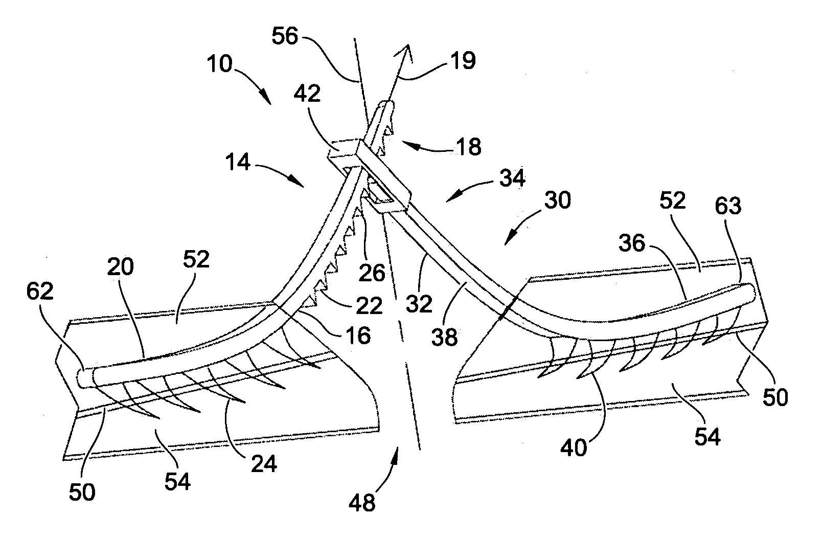
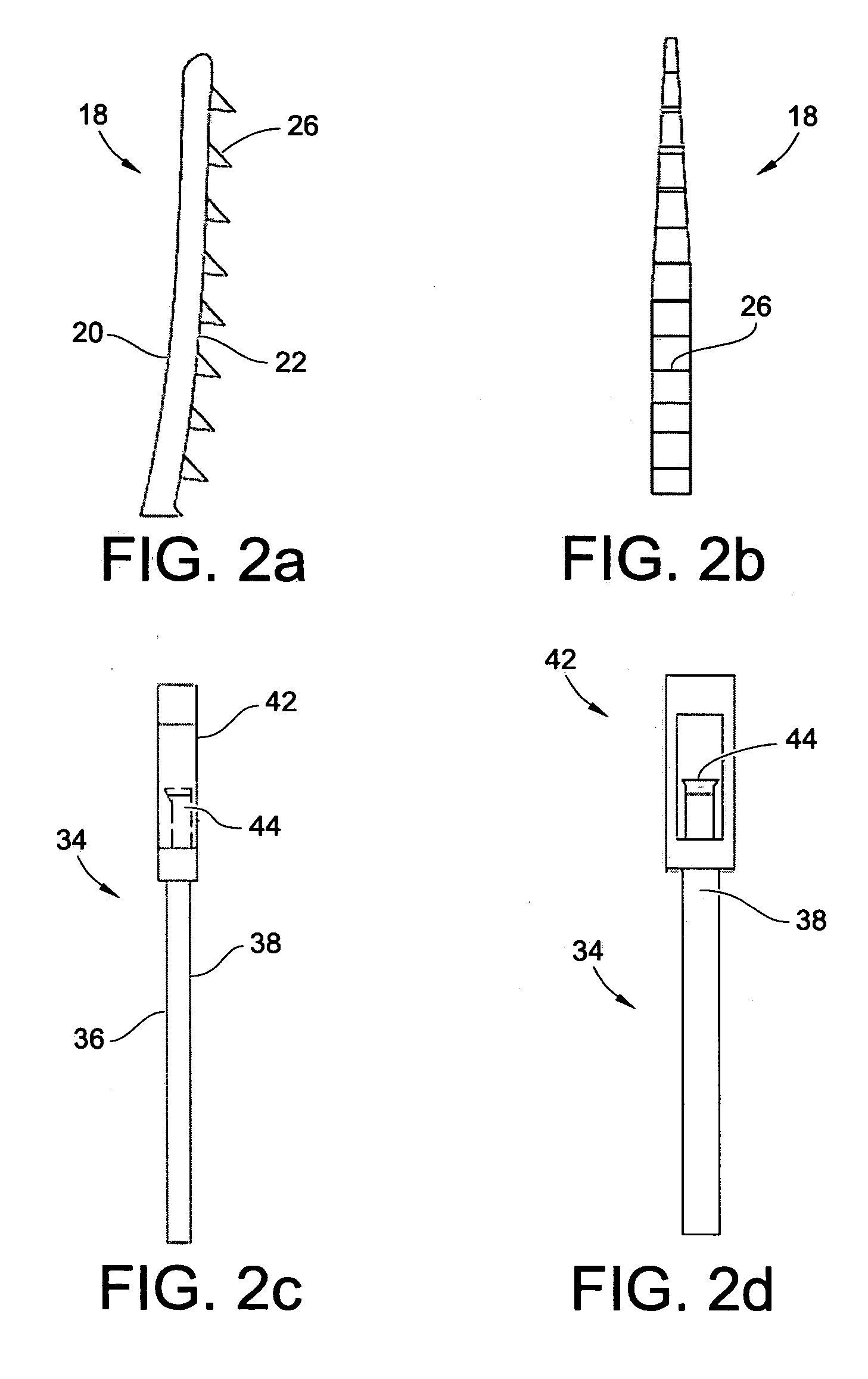
[0057] Referring now to FIG. 1, there is illustrated a perspective view of the disclosed invention 10. As illustrated, the invention 10 includes a first strap 14 and a second strap 30. The first strap 14 and the second strap 30 include distal ends 62 and 63 and proximal ends 18 and 34, respectively. The straps 14 and 30 are planar and made of a pliable material having dorsal surfaces 20 and 36 and a ventral surface 22 and 38. The dorsal surface 20 and 36 of the straps 14 and 30 are smooth while the ventral surfaces 22 and 38 include a plurality of tissue attachment points or small barbs 24 and 40 which project downward from the ventral surface 22 and 38 and curve toward the proximal end 18 and 34. In one preferred embodiment, the straps 14 and 30 have a length of about 4 cm and a width of about 0.5 cm. In other embodiments, the straps 14 and 30 may be larger or smaller to accommodate a wound, illustrated at 48. Although the shape of the straps 14, 30 may include planar sides as illu...

second embodiment

[0070] Reference is now made to FIGS. 4-9 for the invention, which is directed to a wound closure device including a tissue-connecting strap 100 for connecting wound tissue. Advantageously, the tissue-connecting strap 100 can act upon itself thereby eliminating the necessity of mating straps of different configurations. Referring now to FIGS. 4a-f, the tissue-connecting strap 100 is a one-piece unit sectioned into a tissue insertion tongue 102 at the proximal end 106 of the tissue-connecting strap 100 and a forked or U-shaped engagement clasp 104 at the distal end 108 of the tissue-connecting strap 100. The insertion tongue 102 is defined by an upper side 110, which is generally smooth and preferably slightly curved. The lower side 112 is again generally smooth, but is defined by a series of attachment points or barb elements 114 having a base connected to the lower side and a pointed end. Although the figures illustrate ordered rows of barb elements 114 beginning at the distal end ...

third embodiment

[0084] It is within the scope of the third embodiment to use an engagement tool 142 as illustrated in FIGS. 9a and 9b for engagement of the female connector 230 to the tissue-connecting strap 262. Likewise, and as illustrated in FIG. 14, the male connecting strap 200 engages the tissue-connecting strap 262 by similar means as described with respect to FIG. 13.

[0085] It is within the scope of the present invention to eliminate the tissue-connecting and the engagement clasps 208 and 236 of the male connecting strap 200 and female connector 230, respectively, in favor of a molded strap in which the male connecting strap 200 includes the tissue-connecting strap 262 integrally connected thereon and the female connector 230 includes the tissue-connecting strap 262 integrally connected thereon.

[0086] Once the male connecting strap 200 and female connector 230 are placed in the wound tissue, the proximal end 202 of the male connecting strap 200 is urged through the slot 257 in the hinge en...


PUM


Abstract

A device and technique for a sutureless wound closure, which limits the risks of rupture and scarring, is described. The device includes a one-piece surgical fastener generally shaped in a curve along the width of the surgical fastener. The fastener includes a tissue insertion tongue with a plurality of tissue attachment points for fixing the fastener to skin tissue. The fastener also includes a clasp for engaging an identical surgical fastener. The surgical fastener can also be a two-piece structure including a male connecting strap and a female connector. Both pieces include a tissue-connecting mechanism for fixing to skin tissue. The female connector includes an engagement clasp for securing the male connecting strap to the female connector.

Description

RELATED APPLICATIONS [0001] This application is a continuation-in-part to U.S. patent application Ser. No. 10 / 607,650, filed Jun. 27, 2003, in the name of Dennis D. Garvin, and entitled “Device for Sutureless Wound Closure,” the contents of which are incorporated herein by reference.FIELD OF THE INVENTION [0002] The present invention relates to a surgical fastener and technique for its use. Specifically, the invention is directed to a device to close wounds without the use of sutures. [0003] This application claims priority to U.S. Provisional Patent Application No. 60 / 720,779, filed Sep. 27, 2005, in the names of Dennis D. Garvin and Jeffrey P. Wong, entitled “Device for Surgical Repair, Closure, and Reconstruction,” the contents of which are incorporated herein by reference. DESCRIPTION OF THE PRIOR ART [0004] Classical techniques to close wounds and incisions use sutures, basically using a needle and thread to sew the wound closed. While this technique acts to stitch the respecti...

Claims


Application Information

Patent Timeline
IPC IPC(8): A61B17/08
CPCA61B17/08A61B2017/00792A61B2017/06176Y10T24/3499A61B2017/00796Y10S24/48A61B2017/086
Inventor GARVIN, DENNIS D.WONG, JEFFREY P.
Owner SURGICAL SECURITY
Why Eureka
Try Eureka