High-pressure processing apparatus

a processing apparatus and high-pressure technology, applied in the direction of photomechanical treatment originals, cleaning using liquids, instruments, etc., can solve the problems of slow processing speed, difficult to keep the uniformity of the surface treatment of the substrate, and decrease the throughput, so as to improve the solubility of the chemical agent in the supercritical fluid on carbon dioxide, and the solubility of the chemical agent is extraordinary.

Inactive Publication Date: 2007-02-01
DAINIPPON SCREEN MTG CO LTD
View PDF4 Cites 18 Cited by
  • Summary
  • Abstract
  • Description
  • Claims
  • Application Information

AI Technical Summary

Benefits of technology

[0017] In case that a mixture of the high-processing fluid and the chemical agent is used as a processing fluid and that a solubility of the chemical agent functioning as a cleaning component in the high-pressure fluid is low, it is preferable to use a compatibilizer which can serve as an auxiliary agent dissolving or evenly diffusing the cleaning component in the high-pressure fluid. Especially, when the chemical agent contains humidity, solubility of the chemical agent in a supercritical fluid on carbon dioxide becomes extraordinary. Even if the solubility between the high-pressure fluid and the chemical agent including several components is low, addition of the compatibilizer makes the solubility be improved. This compatibilizer has a function that is for removing the chemical agent which remains onto the surface of the substrate in a rinse step after a cleaning step.

Problems solved by technology

Hence, the apparatus has problems of slowing the processing speed and decreasing the throughput.
As a result, it is hard to keep the uniformity of the surface treatment for the substrate.
However, as a matter of fact, it is very difficult to shape into such disc-like (this includes the disc itself shape and the shape of the distribution holes and the setting place of the holes) with high accuracy.
As the SCF introduced along a fluid inlet path is blew off from the distribution holes so as to be dispersed to all over the surface of the substrate, the speed of the SCF which is vertically incidence to the surface from each distribution hole is getting slow.
As a result, the processing efficiency per dimension is decreased.

Method used


Image

  • High-pressure processing apparatus
  • High-pressure processing apparatus
  • High-pressure processing apparatus

Examples


first embodiment

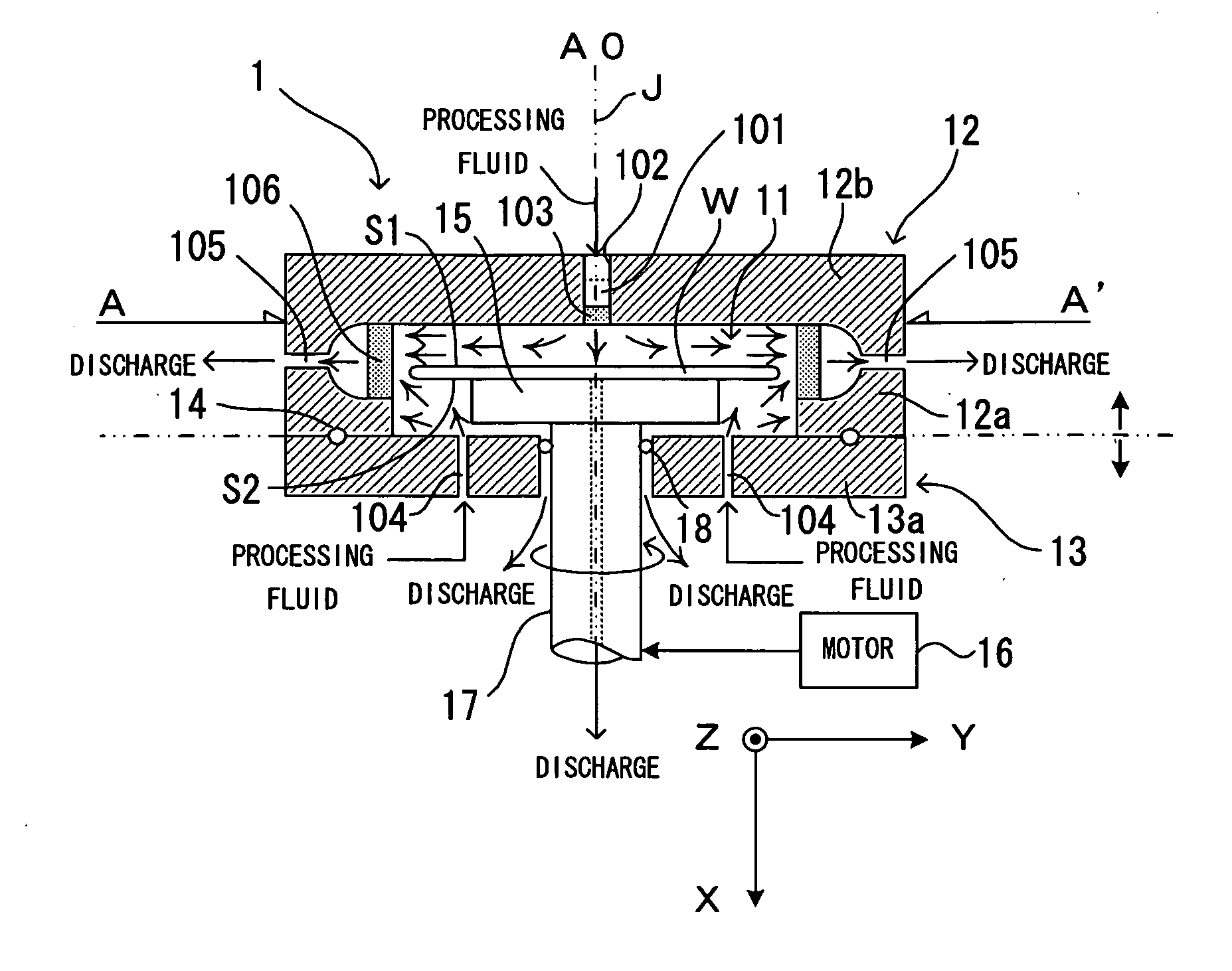
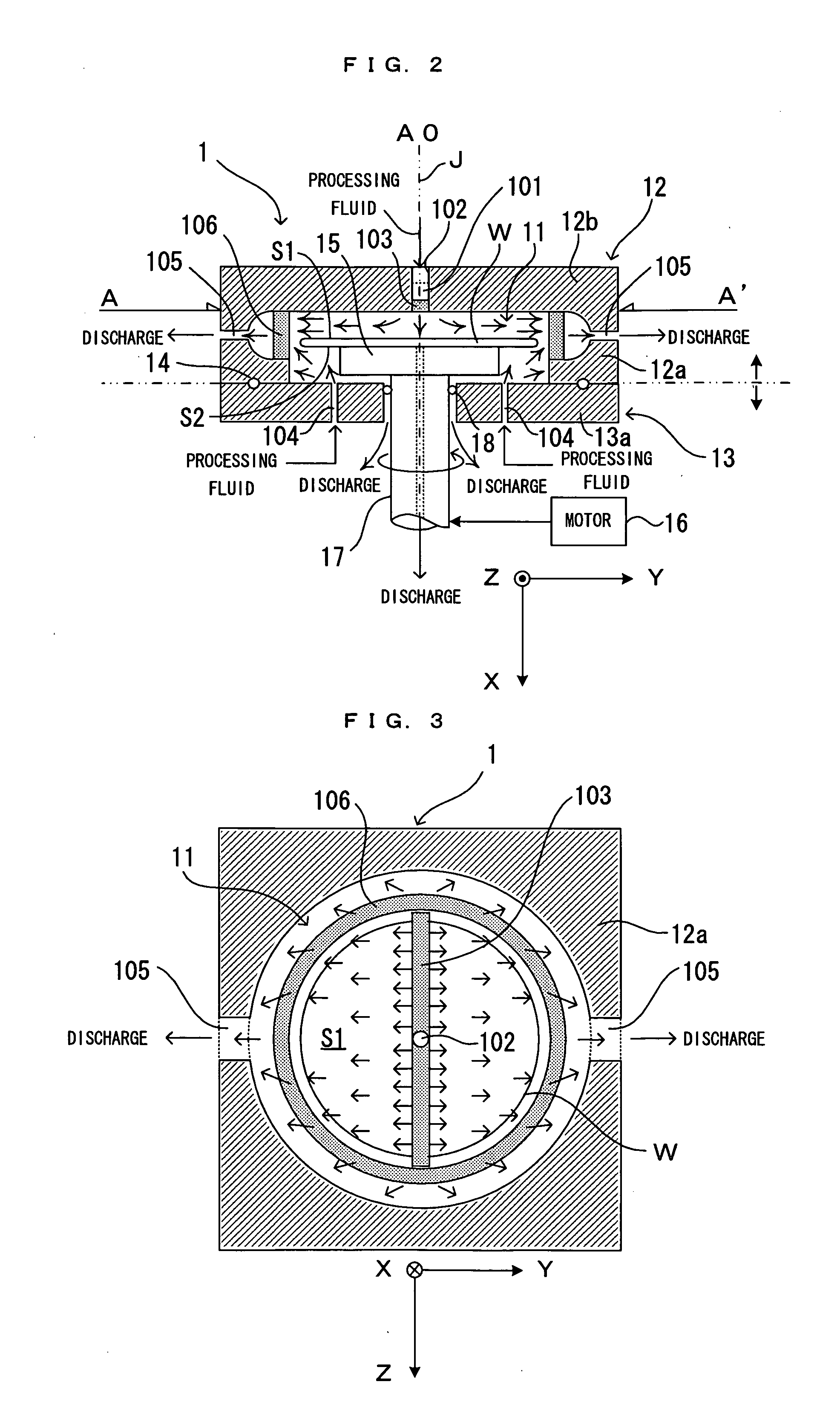
[0033]FIG. 1 is a diagram showing an entire structure of a first embodiment of a high-pressure processing apparatus according to the present invention. FIG. 2 is a view showing a pressure vessel and an inner structure thereof in the high-pressure processing apparatus shown in FIG. 1. FIG. 3 is a top view of the pressure vessel taken from above along the line A-A′. This high-pressure processing apparatus is an apparatus which introduces supercritical carbon dioxide (high-pressure fluid) or a mixture of supercritical carbon dioxide and a chemical agent, as a processing fluid, into a processing chamber 11 which is formed inside a pressure vessel 1, thereby performing predetermined cleaning and drying processes for a subround substrate (object-to-be-processed) W, such as a semiconductor wafer, which is held in the processing chamber 11. Hereinafter, structure and operation of the high-pressure processing apparatus will be described in detail.

[0034] In the high-pressure processing appar...

second embodiment

[0064]FIG. 6 is a view showing a pressure vessel and an inner structure thereof in a second embodiment of a high-pressure processing apparatus according to the present invention. FIG. 7 is a top view of the pressure vessel taken from above along the line B-B′. FIG. 8 is a diagram showing an arrangement of pipes which deliver a processing fluid to the pressure vessel in the second embodiment. This second embodiment has the common with the first embodiment in a specific structure in which a processing fluid is fed toward a surface S1 of a substrate W from a slit delivery path 201 elongating along a direction Z. However a large difference are the way of discharging the processing fluid and the way of supplying the processing fluid additionally from edge sides of the substrate W. Hereinafter, the point of difference in the structure and the operation between the first embodiment and the second embodiment will be described.

[0065] In this second embodiment, there are three opening slits ...


PUM

PropertyMeasurementUnit
pressureaaaaaaaaaa
pressureaaaaaaaaaa
pressureaaaaaaaaaa

Abstract

Processing fluid is vertically incident to a surface S1 of a rotation substrate W through a delivery path provided on a pressure vessel. The curtain of processing fluid has a width longer than a diameter of the substrate. Therefore, a cleaning process is execute onto the whole surface of the substrate by the processing fluid.

Description

CROSS REFERENCE TO RELATED APPLICATION [0001] The disclosure of Japanese Patent Application No. 2005-220702 filed Jul. 29, 2005 including specification, drawings and claims is incorporated herein by reference in its entirety. BACKGROUND OF THE INVENTION [0002] 1. Field of the Invention [0003] The present invention relates to a high-pressure processing apparatus. The apparatus cause a processing fluid to come into contact with a surface of an object-to-be-processed such as a substrate, thereby performing a predetermined surface treatment (e.g. developing, cleaning, drying or the like) for the surface of the object-to-be-processed. The processing fluid includes a high-pressure fluid or a mixture of a high-pressure fluid and a chemical agent. [0004] 2. Description of the Related Art [0005] Conventionally proposed is a technique of a high-pressure cleaning process which sets up a substrate within a pressure vessel and uses a supercritical fluid (hereinafter referred to as “SCF”) having ...

Claims


Application Information

Patent Timeline
Patent Type & Authority Applications(United States)
IPC IPC(8): B05C13/02C23C14/00B08B3/02G03F1/82H01L21/304
CPCH01L21/67051B08B3/02
Inventor SAITO, KIMITSUGU
Owner DAINIPPON SCREEN MTG CO LTD
Why Eureka
Try Eureka