Method and apparatus for controlling the charge of a bootstrap capacitor for non-synchronous type DC-DC converter

a dc-dc converter and bootstrap capacitor technology, applied in the direction of electric variable regulation, process and machine control, instruments, etc., can solve the problems of not being able to fully turn on the driver of the power transistor, the efficiency of the dc-dc converter is suffering, and the bootstrap capacitor may not be fully charged at light load or no load conditions

Active Publication Date: 2007-02-01
NUVOTON TECH CORP JAPAN +1
View PDF2 Cites 29 Cited by
  • Summary
  • Abstract
  • Description
  • Claims
  • Application Information

AI Technical Summary

Benefits of technology

[0009] The purpose of this invention is to provide a method to control the charge in the bootstrap capacitor for step-down converter which operates under the light load or no load condition without the efficiency loss.

Problems solved by technology

This may not be enough to fully turn on the driver for the power transistor.
One problem with this simple method is that the efficiency of the dc-dc converter is suffered because the current in the dummy load always flows to ground, even when the bootstrap capacitor voltage is high enough.
One problem of the conventional bootstrap method is that the bootstrap capacitor may not be fully charged at light load or no load conditions.
When the Vout is close to VREF, or even worse when Vout is higher than VREF, there may not be enough charging to the bootstrap capacitor.
The situation becomes worse when there is no load current drawing from the output of the DC-DC converter.
So the bootstrap capacitor could not be charged to an enough high level to turn on the driver circuit when the load current becomes heavy after the light load condition and the switching of the power transistor is required.
But this method will reduce the efficiency of the DC-DC converter for all the conditions.

Method used


Image

  • Method and apparatus for controlling the charge of a bootstrap capacitor for non-synchronous type DC-DC converter
  • Method and apparatus for controlling the charge of a bootstrap capacitor for non-synchronous type DC-DC converter
  • Method and apparatus for controlling the charge of a bootstrap capacitor for non-synchronous type DC-DC converter

Examples


first embodiment

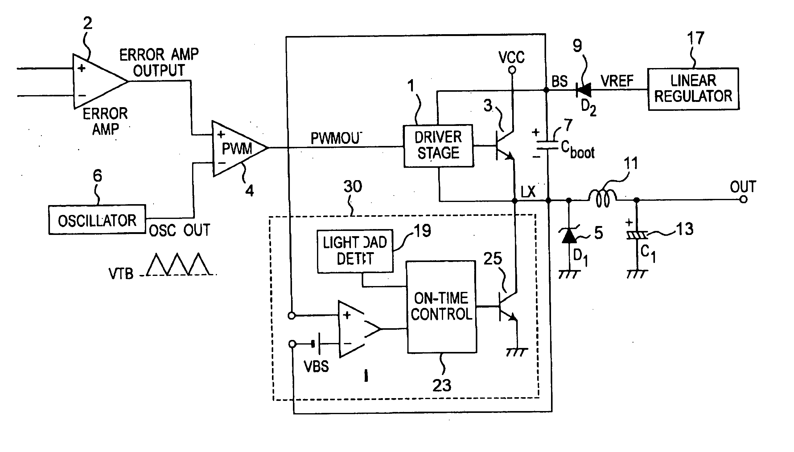
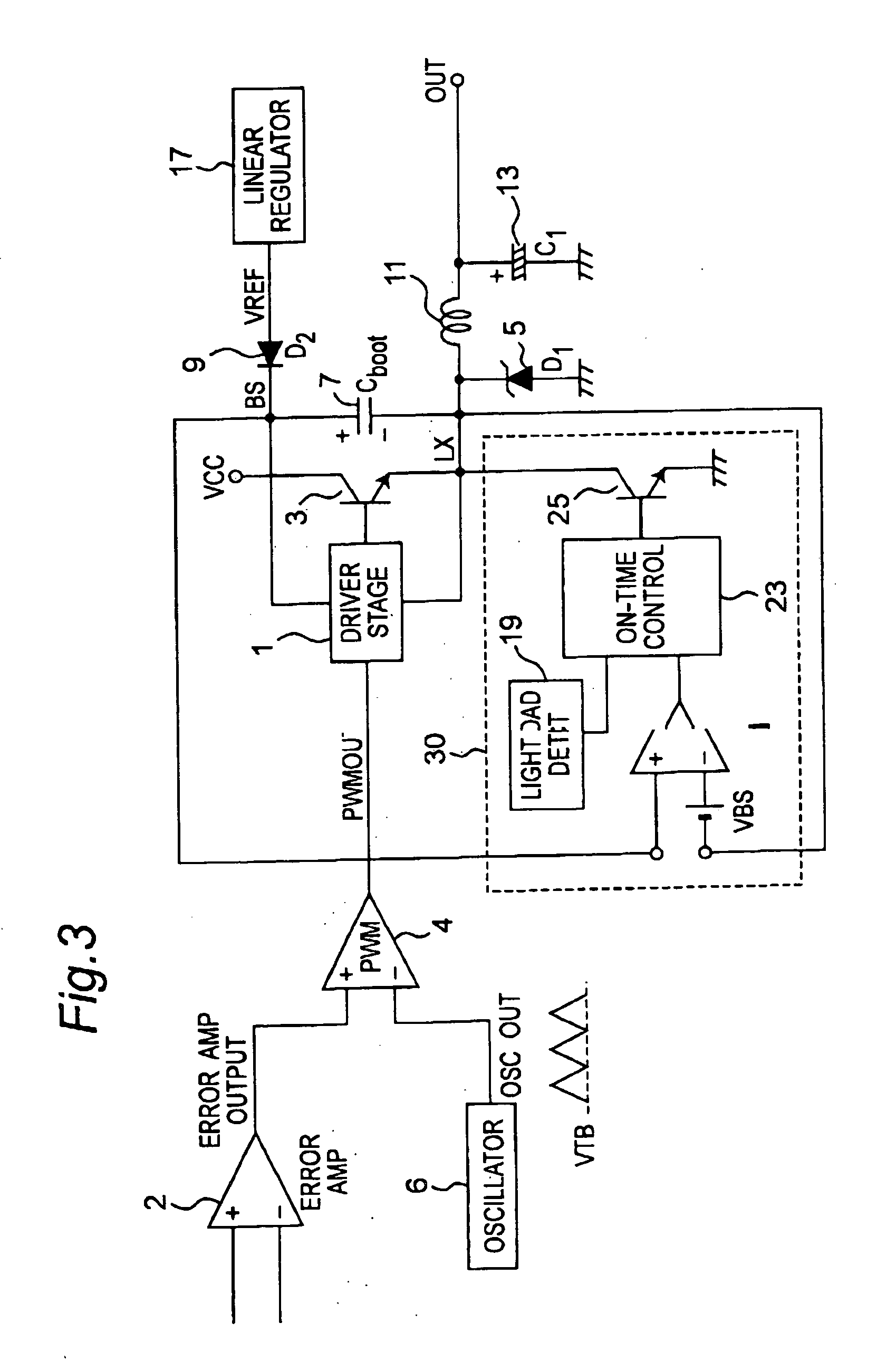
[0045] Referring to FIG. 3, a first embodiment of a non-synchronous DC-DC converter according to the present invention is shown.

[0046] The DC-DC converter has an error amplifier 2, an oscillator 6, a pulse width modulation (PWM) circuit 4, a driver stage 1, a power transistor 3, a linear regulator 17, a diode 9, a bootstrap capacitor 7, a diode 5, an inductor 11, a capacitor 13, and a control circuit 30. The load control circuit 30 has a BS (bootstrap) voltage detector 21, a light load detector 19, an on-time control 23 and a secondary switch 25 formed by a transistor 25. The secondary switch 25 can be formed by a plurality of transistors.

[0047] Here a bipolar power transistor 3 is used, but can be any other type, such as a NMOS transistor or an N-type DMOS transistor. The bootstrap capacitor 7 is connected between the cathode of the diode 9 and a switching node LX. Here, LX is also used as a voltage level at the node LX. The voltage regulator 17 is connected to the anode of the d...

second embodiment

[0053] Referring to FIG. 6, a second embodiment of a non-synchronous DC-DC converter with maximum duty limit according to the present invention is shown.

[0054] The second embodiment shown in FIG. 6 differs from the first embodiment of FIG. 3 in that the second embodiment does not have a light load detector 19. The elements in FIG. 6 are numbered with the same reference number as that used in FIG. 3 and have the same function as that of FIG. 3. The on-time of the secondary transistor 25 is determined by the duration when the maximum voltage is higher than the ramping signal, or by using the same method as described in FIG. 5.


PUM


Abstract

A method of controlling the charge of the bootstrap capacitor during light load or no load conditions for a non-synchronous type of DC-DC converter consists of bootstrap capacitor voltage detector, light load detector and secondary switch controller. By turning on the secondary switch during the off-time of the power transistor when the bootstrap voltage is lower than the required value under light load condition, the bootstrap capacitor voltage will be able to charge back to the required value, yet minimizing the minimum current requirement for the DC-DC converter.

Description

BACKGROUND OF THE INVENTION [0001] The present invention relates to a non-synchronous dc-dc converter having a bootstrap capacitor and a control circuit and, more particularly, to a method for controlling the charge of a bootstrap capacitor for non-synchronous type DC-DC converter, and also to an apparatus for controlling the charge of a bootstrap capacitor for non-synchronous type DC-DC converter. [0002] In an integrated step-down dc-dc converter system, the power device is usually NPN transistor in bipolar technology, NMOS in CMOS technology or N-type DMOS in BCD technology. Bootstrapping is often used to raise the driver voltage above the power rail in order to reduce the loss of the top power transistor. P-type transistor is not commonly used due to the relatively large area needed, which is about 2-3 times larger than the n-type counterpart. [0003] For a non-synchronous DC-DC converter, in normal operation when load current is high enough, the bootstrap capacitor is charged by ...

Claims


Application Information

Patent Timeline
Patent Type & Authority Applications(United States)
IPC IPC(8): G05F1/00
CPCH02M3/1588Y02B70/16Y02B70/1466H02M2001/0032H02M1/0032Y02B70/10
Inventor WONG, SHIAH SIEWYU, GUOLEI
Owner NUVOTON TECH CORP JAPAN
Why Eureka
Try Eureka