
Vertical comb actuator radio frequency micro-electro-mechanical system switch

Active Publication Date: 2007-02-01
SAMSUNG ELECTRONICS CO LTD
View PDF6 Cites 8 Cited by
  • Summary
  • Abstract
  • Description
  • Claims
  • Application Information

AI Technical Summary

Benefits of technology

[0013] Accordingly, it is an aspect of the present invention to provide an RF MEMS switch, which generates an electrostatic force between a fixing portion and an actuator so that the actuator is prevented from sticking to the substrate, uses a comb actuator structure so that the switch is driven with a low voltage, and has one contact point so that insertion loss and power loss are reduced.

Problems solved by technology

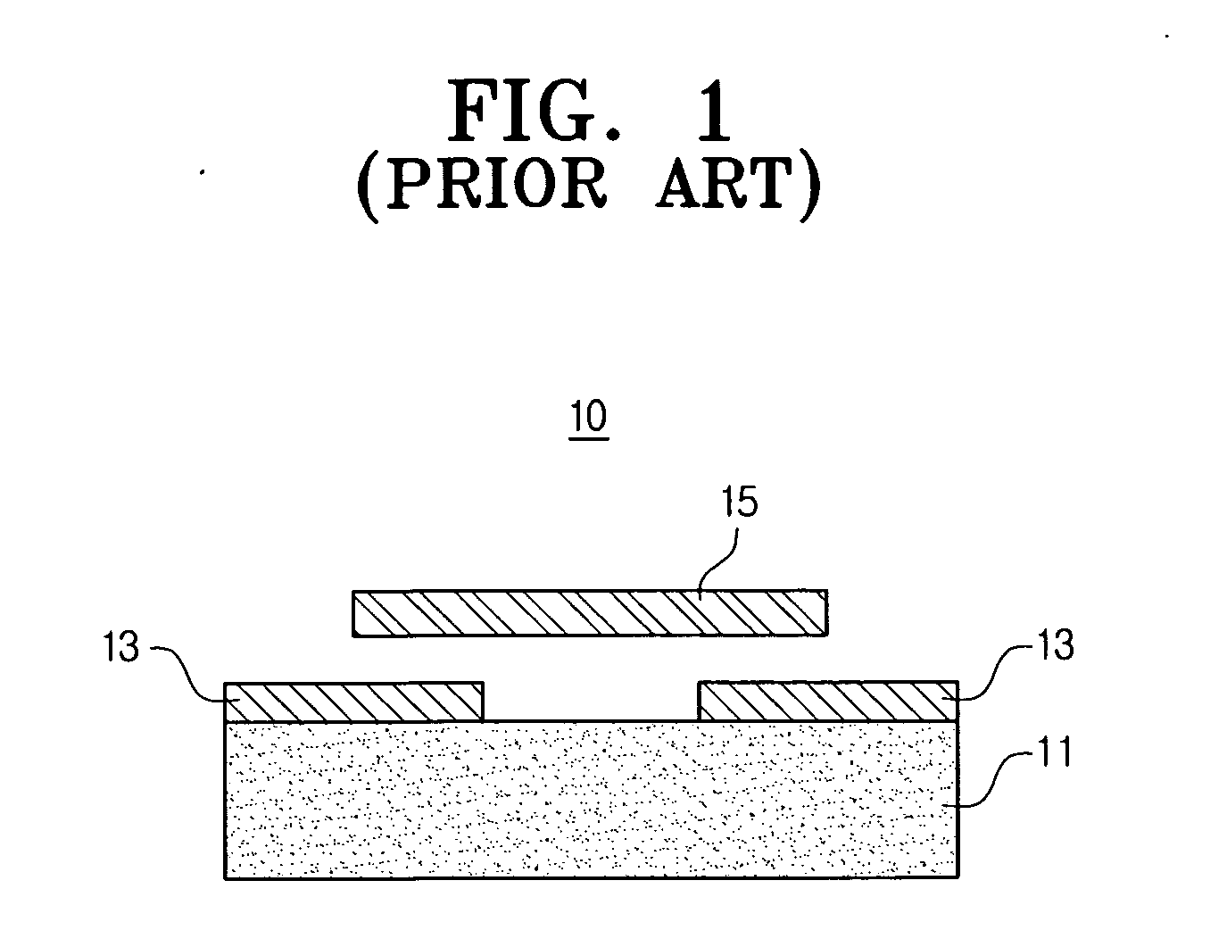
Accordingly, semiconductor switches, such as field effect transistor (FET) switches or pin diodes, which have been used to control signals in such systems have several drawbacks associated with bandwidth, isolation, insertion loss, power consumption, and linearity.
This obstructs the reduction of contact resistance and in turn increases insertion loss and power consumption.

Method used


Image

  • Vertical comb actuator radio frequency micro-electro-mechanical system switch
  • Vertical comb actuator radio frequency micro-electro-mechanical system switch
  • Vertical comb actuator radio frequency micro-electro-mechanical system switch

Examples


Embodiment Construction

[0031] Hereinafter, exemplary embodiments of the present invention will be described with reference to the accompanying drawings.

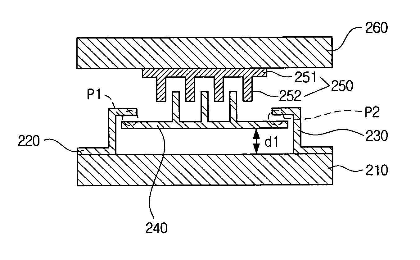
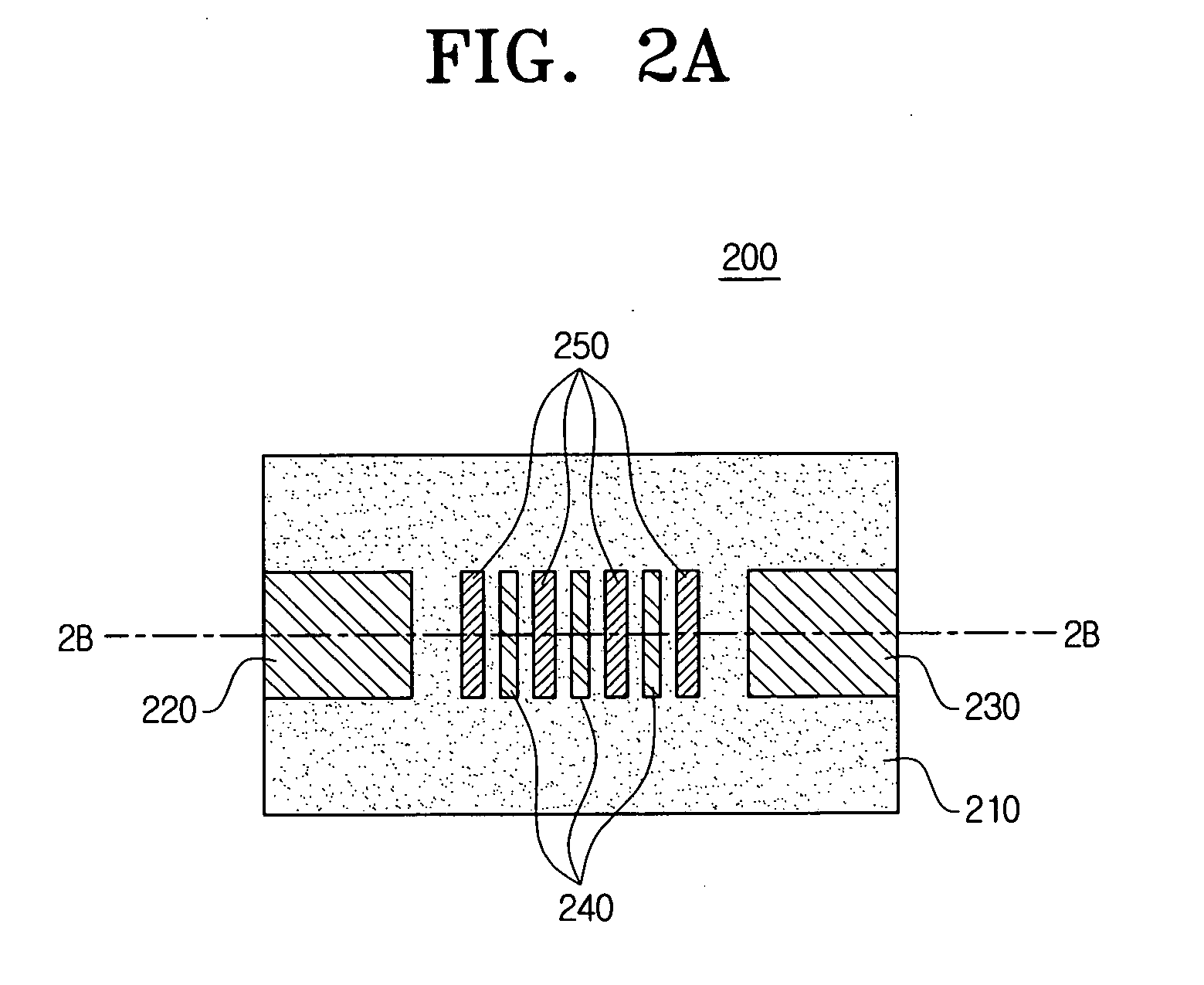
[0032]FIG. 2A is a plan view illustrating the structure of an RF MEMS switch according to an exemplary embodiment of the present invention, and FIG. 2B is a vertical-sectional view taken along line 2B-2B of FIG. 2A.

[0033] Referring to FIGS. 2A and 2B, the RF MEMS switch 200 comprises a lower substrate 210, a first signal line 220, a second signal line 230, an actuator 240, a fixing portion 250, and an upper substrate 260.

[0034] The first signal line 220 and the second signal line 230 are spaced at a predetermined interval from each other and are deposited on the lower substrate 210. The actuator 240 is spaced at a predetermined interval d1 from the lower substrate 210. That is, the actuator 240 performs a switching operation in a bridge form. Further, the actuator 240 has a comb structure in an upward direction.

[0035] If the RF MEMS switch 200 is turne...


PUM


Abstract

A vertical comb actuator radio frequency (RF) micro-electro-mechanical system (MEMS) switch. The RF MEMS switch includes a substrate; first and second signal lines spaced at a predetermined interval from each other and deposited on an upper surface of the substrate; an actuator positioned over the first and second signal lines when viewed from the upper surface of the substrate and spaced at a predetermined interval from the first and second signal lines; and a fixing portion positioned over the actuator when viewed from the upper surface of the substrate, wherein the fixing portion permits the actuator to come in contact with the first and second signal lines when a predetermined driving voltage is applied. Thus, it is possible to prevent the actuator from sticking to the substrate. In addition, the RF MEMS switch can be operated with a low voltage and insertion loss and power loss can be reduced.

Description

CROSS-REFERENCE TO RELATED APPLICATIONS [0001] This application claims priority from Korean Patent Application No. 10-2005-0069374, filed Jul. 29, 2005 in the Korean Intellectual Property Office, the entire contents of which are incorporated herein by reference. BACKGROUND OF THE INVENTION [0002] 1. Field of the Invention [0003] Apparatuses consistent with the present invention relate in general to a radio frequency (RF) micro-electro-mechanical system (MEMS) switch, and more particularly, to an RF MEMS switch in which electrostatic force is generated between a fixing portion and an actuator so that the actuator is prevented from sticking to a substrate. [0004] 2. Description of the Related Art [0005] A MEMS refers to a device or system in which electric components and mechanical components are combined in a small structure. An RF MEMS refers to an RF device or system having the MEMS. The MEMS increases performance, the number of functions, and integration of the RF device, and lowe...

Claims


Application Information

Patent Timeline
IPC IPC(8): H01P1/10
CPCH01H59/0009H01H59/00H01H2237/004
Inventor HONG, YOUNG-TACKYUN, SEOK-CHULCHANG, SEOK-MOKWON, SANG-WOOKKIM, CHE-HEUNGKIM, JONG-SEOKJEONG, HEE-MOONLEE, SANG-HUNKIM, JUN-OSONG, IN-SANG
Owner SAMSUNG ELECTRONICS CO LTD
Learn More