Fluid bearing device

a technology of bearings and fluids, which is applied in the direction of bearing rigid support, sliding contact bearings, mechanical equipment, etc., can solve the problems of static electricity charging becoming a problem, the conductivity of the housing becoming inadequate, and the inability to reliably discharge static electricity to the ground, etc., to achieve the effect of reducing the cost of assembly, and reducing the manufacturing cost of the housing

Inactive Publication Date: 2007-02-01
NTN CORP
View PDF13 Cites 29 Cited by
  • Summary
  • Abstract
  • Description
  • Claims
  • Application Information

AI Technical Summary

Benefits of technology

[0014] By producing the housing from a resin in this manner, the housing can be formed with high precision and at low cost using a molding process such as injection molding. Particularly if the housing is formed by resin molding (insert molding) with the bearing sleeve as an insert component, the operation of assembling the housing and the bearing sleeve becomes unnecessary, enabling further reductions in the cost of assembly.
[0059] According to the present invention, a fluid bearing device can be provided which enables a reduction in the manufacturing costs of the housing, and also enables a more efficient assembly process, thereby offering even lower costs. Furthermore, according to the present invention, the molding precision of a housing produced by resin injection molding can be improved. In addition, according to the present invention, the problem of a reduction in oil repellency at the gate removal portion of a housing produced by resin injection molding can be resolved.

Problems solved by technology

However, because resins are normally insulating materials, a resin housing such as that described above would be unable to discharge accumulated static electricity through the housing and to ground, meaning charging caused by static electricity becomes a problem.
If the volume resistivity exceeds 106 Ω·cm, then the conductivity of the housing becomes inadequate, and even if the conducting means enables conductivity to be achieved between the shaft member and the housing, the static electricity can still not be reliably discharged to ground.

Method used


Image

  • Fluid bearing device
  • Fluid bearing device
  • Fluid bearing device

Examples


Embodiment Construction

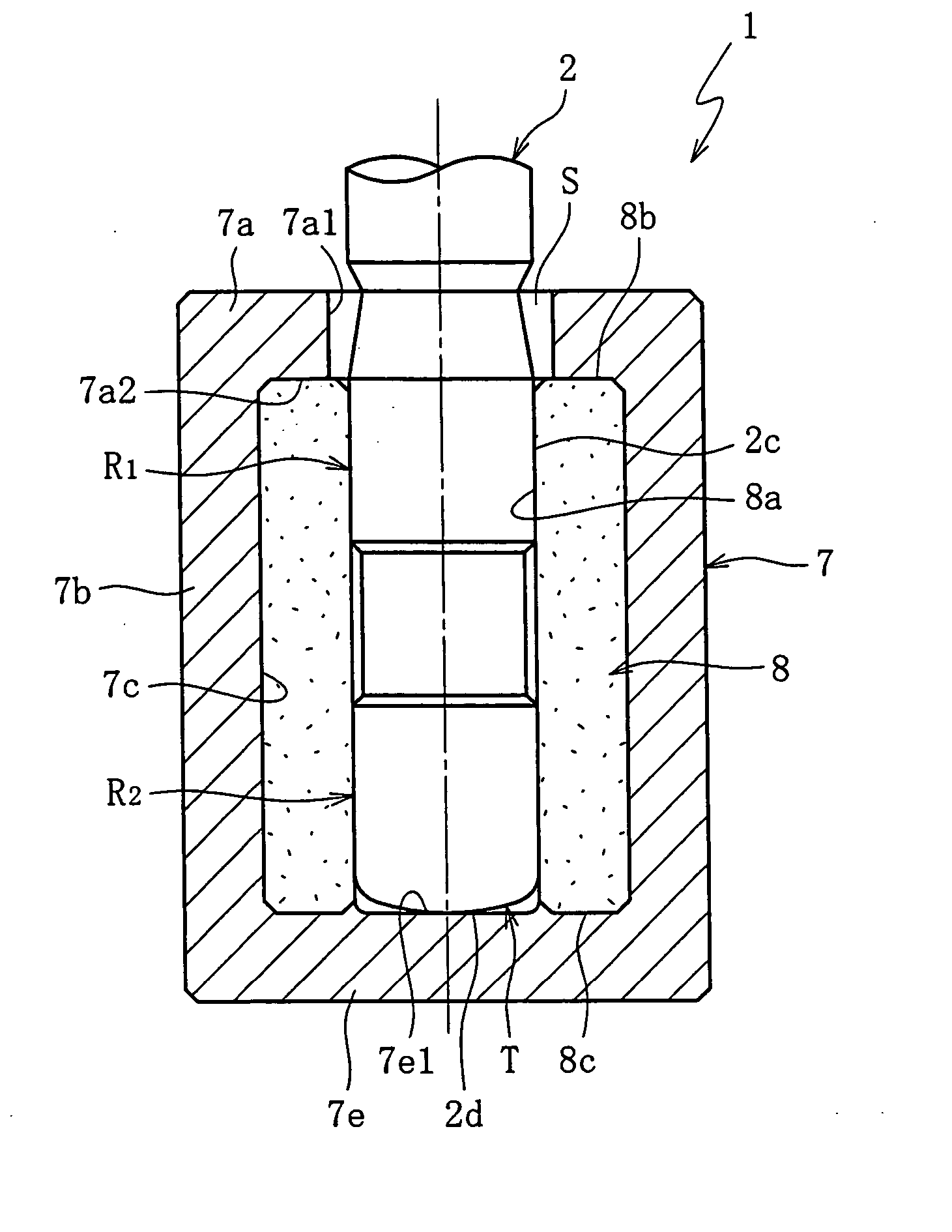
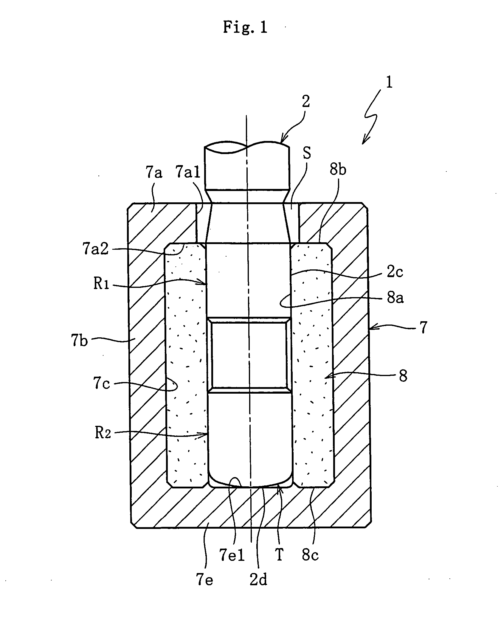
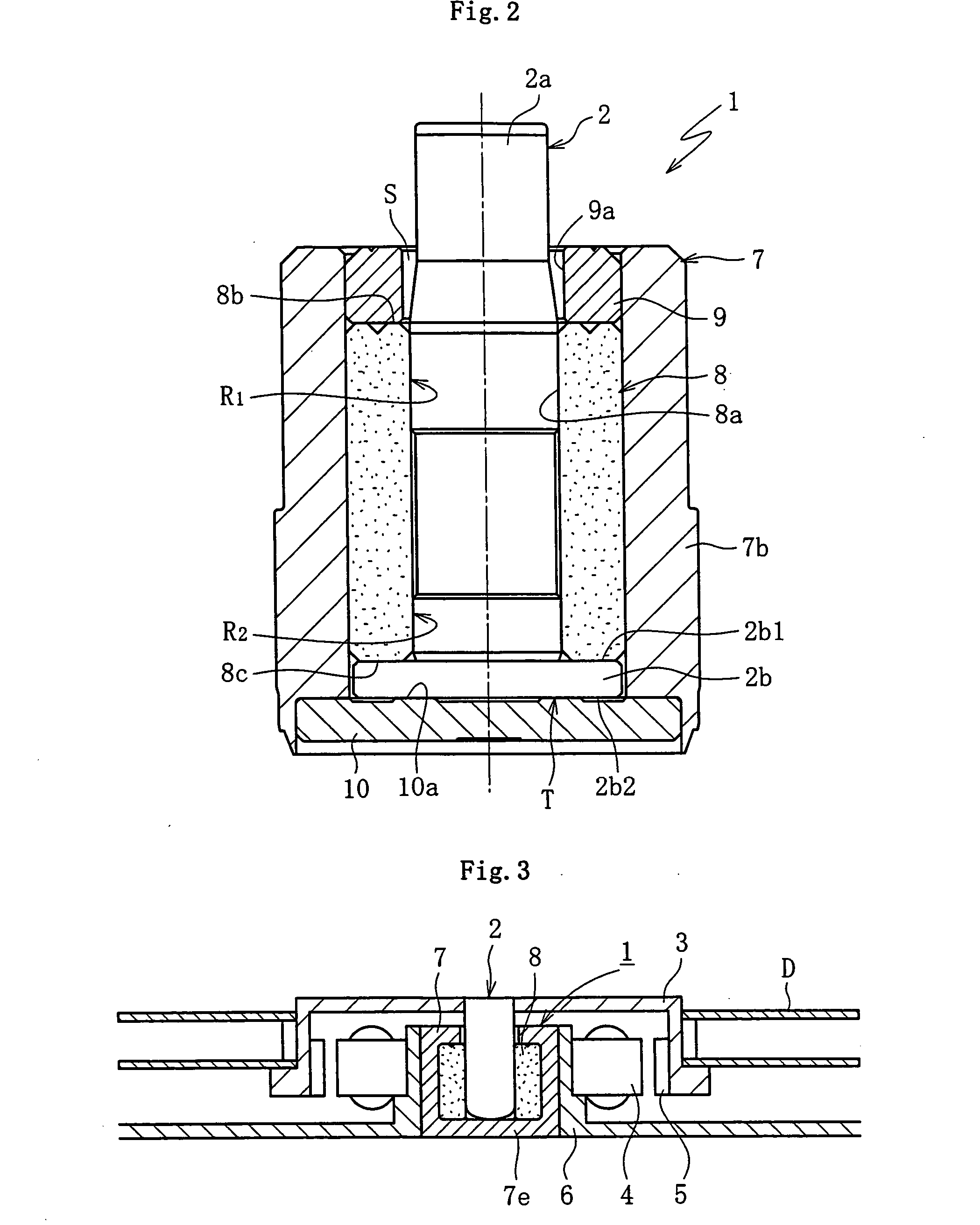
[0074] Preferred embodiments of the present invention will be hereinafter described, based on FIG. 1 to FIG. 3.

[0075]FIG. 3 shows one possible construction for a spindle motor for information-processing equipment, incorporating a fluid bearing device 1 according to this embodiment. This spindle motor is used in a disk drive device for HDD or the like, and comprises a fluid bearing device 1 which supports a shaft member 2 in a freely rotatable, non-contact manner, a disk hub 3 which is mounted onto the shaft member 2 using press fitting or the like, and a motor stator 4 and a motor rotor 5 which oppose one another across a gap in the radial direction. The stator 4 is attached to the outer periphery of a casing 6, and the rotor 5 is attached to the inner periphery of the disk hub 3. A housing 7 for the fluid bearing device 1 is mounted to the inner periphery of the casing 6. Either one disk or a plurality of disks D such as magnetic disks are supported by the disk hub 3. When current...


PUM

PropertyMeasurementUnit
volume resistivityaaaaaaaaaa
particle sizeaaaaaaaaaa
lengthaaaaaaaaaa

Abstract

A fluid bearing device which enables cost reductions and prevents static electricity charging. A bearing sleeve is secured inside a housing, and a shaft member is inserted inside an inner peripheral surface of the bearing sleeve. A lubricating oil dynamic pressure effect is used to generate pressure within a bearing gap between the inner peripheral surface of the bearing sleeve and an outer peripheral surface of the shaft member, thereby supporting the shaft member in a non-contact manner in the radial direction. An axial end portion of the shaft member contacts a housing bottom portion, enabling conductivity between the two members, and the housing is made of a conductive resin composition containing added carbon nanofiber with a volume resistivity of 106 Ω·cm or less.

Description

BACKGROUND OF THE INVENTION [0001] The present invention relates to a fluid bearing device which supports a rotating member in a non-contact manner via a lubricating oil film that is generated within a radial bearing gap and a dynamic bearing device (a fluid dynamic bearing device) which supports a rotating member in a non-contact manner via a lubricating oil dynamic pressure effect that is generated within a bearing gap. These bearing device is ideal for use in information-processing equipment, including the spindle motors for magnetic disk devices such as HDD and FDD, optical disk devices for CD-ROM, CD-R / RW, DVD-ROM / RAM, etc. and magneto-optical disk devices for MD, MO, etc., the polygon scanner motors in laser beam printers (LBP), or as small-scale motors for electrical equipment such as axial flow fans. [0002] In each of the motor types described above, in addition to high rotational precision, other sought after performance factors include increased speed, lower costs, and low...

Claims


Application Information

Patent Timeline
Patent Type & Authority Applications(United States)
IPC IPC(8): F16C32/06F16C17/02F16C17/04F16C17/10F16C17/26F16C33/10H02K5/16H02K11/00
CPCF16C17/107F16C17/26H02K11/0089H02K5/1675H02K11/00F16C33/107F16C2370/12H02K11/40B29C45/38F16C17/10F16C35/02H02K7/08
Inventor SATOJI, FUMINORIITOU, KENJISHIBAHARA, KATSUO
Owner NTN CORP
Why Eureka
Try Eureka